Motor cooling and eddy current suppression structure

a technology of eddy current suppression and motor cooling, which is applied in the direction of windings, magnetism circuit shapes/forms/constructions, propulsion systems, etc., can solve the problems of affecting the accuracy of positioning, affecting the measurement accuracy of sensors, and unable to achieve positioning accuracy, so as to reduce the surface temperature of the motor, inhibit the temperature rise of the motor winding, and ensure the structural strength of the motor

Active Publication Date: 2014-10-23
HARBIN INST OF TECH
View PDF3 Cites 31 Cited by
  • Summary
  • Abstract
  • Description
  • Claims
  • Application Information

AI Technical Summary

Benefits of technology

[0014]The beneficial effects of the present invention is that the new motor cooling and eddy current suppressing structure can effectively inhibit the temperature rise of the motor windings. More importantly the application of non-magnetic metallic materials in the motor cooling and eddy current suppression structure will help to reduce the surface temperature of the motor and ensure the structural strength of the motor. When eddy currents are induced by the relative motion between mental material and magnetic field, the present invention could effectively reduce such eddy currents through the following way. Incorporate slits in the cooling plate to c

Problems solved by technology

Excessive motor temperature rise not only affect its reliability, but also impact on the positioning accuracy as well due to the increase in motor's thermal stress.
Besides, ultra-precision positioning servo system is using a laser displacement sensor for position measurement, therefore, the temperature rise in the motor's surface will result in ambient temperature

Method used


Image

  • Motor cooling and eddy current suppression structure
  • Motor cooling and eddy current suppression structure
  • Motor cooling and eddy current suppression structure

Examples


Embodiment Construction

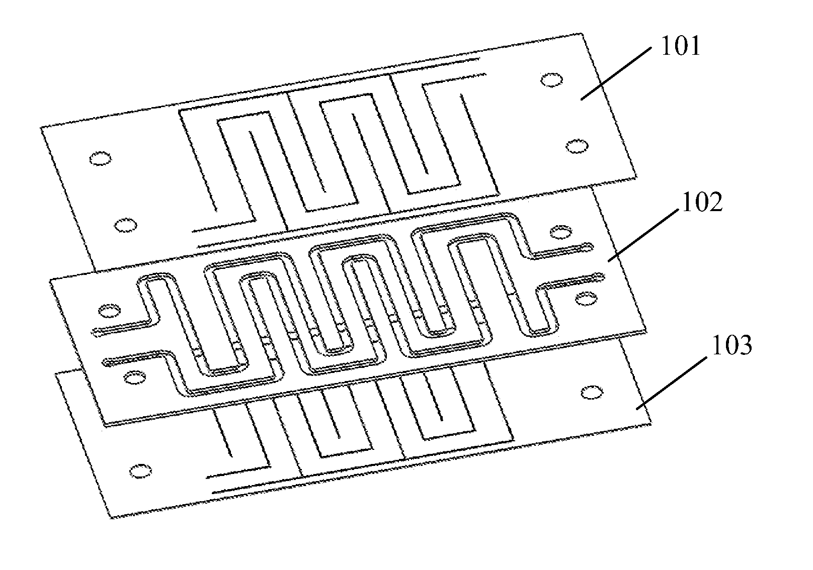
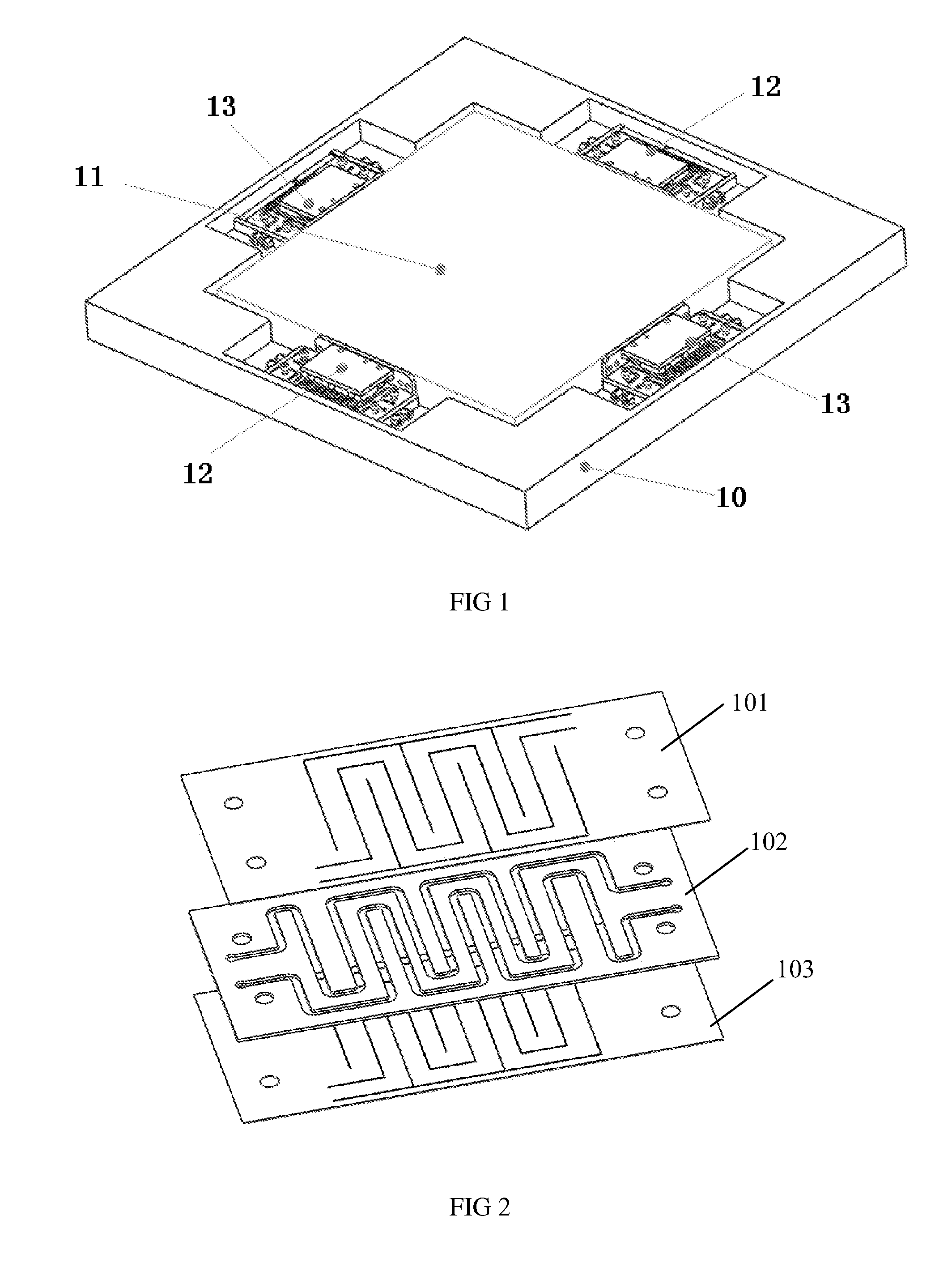
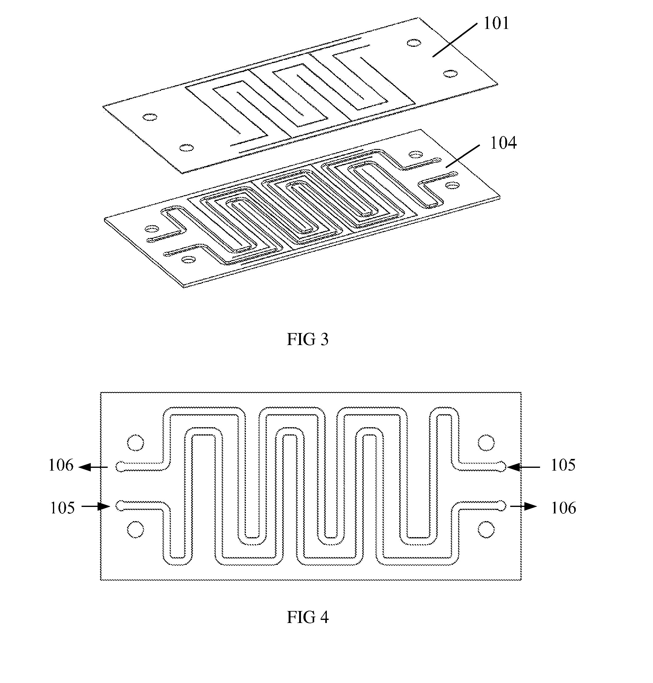
[0034]FIG. 2 to 10 schematically depict a new type motor cooling and eddy current suppression structure 100 according to one embodiment of the invention, which is mounted on the surface of motor winding 201 according to a particular embodiment of the invention. This new type cooling and suppression structure comprises: a first cooling plate 101; a second cooling plate 103; a cooling water circuit: locate in between the first cooling plate 101 and the second cooling plate 103 for allowing the coolant to get through.

[0035]FIGS. 2 and 3 show that the new motor cooling and eddy current suppression structure 100 can be constructed in two different forms.

[0036]As shown in FIG. 2, the new motor cooling and eddy current suppression structure 100 consists of three layers, including the first cooling plate 101, the second cooling plate 103 and a wire-slitted cooling plate 102. By using the sealant, the first and the second cooling plates (101 and 103) are attached to both sides of the third c...


PUM


Abstract

A motor cooling and eddy current suppression structure (100), which is attached to the surface of the motor winding (201), includes a first cooling plate (101), a second cooling plate (103,104), and a cooling water circuit located between the first cooling plate and the second cooling plate. The cooling water circuit is configured to allow the cooling fluid to pass through. The first and the second cooling plates are both non-magnetic metallic materials. The first cooling plate is divided into a plurality of individual first regions (301,303) which are corresponding to each pole of the motor by one or more first slits (305) provided on the first cooling plate in the position where the motor poles are combined. Each of the first regions is further divided into an even number of first sub-areas by at least one fist sub-slit (306) where induced electromotive force is generated. Two adjacent first sub-areas in respective first regions are grouped together, and the ends of each first sub-area that has the same polarity are connected in series. The second cooling plate is divided into a plurality of individual second regions which are corresponding to each pole of the motor by one or more second slits provided on the second cooling plate in the position where the motor poles are combined. Each of the second regions is further divided into an even number of second sub-areas by at least one second sub-slit where induced electromotive force is generated. Two adjacent second sub-areas in respective second regions are grouped together, and the ends of each second sub-area that has the same polarity are connected in series. This structure can efficiently reduce the temperature of the motor winding and reduce the induced eddy current.

Description

FIELD OF INVENTION[0001]The present invention relates to the field of motor cooling, and in particular, to a new motor cooling and eddy current suppressing structure.BACKGROUND OF THE INVENTION[0002]Ultra precision positioning servo system places severe constraints on the amount of heat can be produced by actuator (motor), and its trust control accuracy. FIG. 1 shows the application of linear motor in ultra precision positioning servo system. On the basic frame 10, there are two X-axis linear motors 12 and two y-axis linear motors 13 to drive and locate the load 11 in a desirable position. Excessive motor temperature rise not only affect its reliability, but also impact on the positioning accuracy as well due to the increase in motor's thermal stress. Besides, ultra-precision positioning servo system is using a laser displacement sensor for position measurement, therefore, the temperature rise in the motor's surface will result in ambient temperature changes and affecting the measur...

Claims


Application Information

Patent Timeline
IPC IPC(8): H02K1/20
CPCH02K1/20H02K41/0356H02K3/24H02K3/47H02K16/00H02K2201/18H02K9/227H02K9/22
Inventor LI, LIYIPAN, DONGHUA
Owner HARBIN INST OF TECH
Why Eureka
Try Eureka