Radio apparatus

a radio apparatus and antenna technology, applied in the direction of pivotable antennas, antenna details, antennas, etc., can solve the problems of inconvenient use of radio apparatuses with two or more narrow-band antennas, large size and complicated configuration, and difficulty in forming thin cases

Inactive Publication Date: 2006-09-05
GK BRIDGE 1
View PDF5 Cites 31 Cited by
  • Summary
  • Abstract
  • Description
  • Claims
  • Application Information

AI Technical Summary

Problems solved by technology

Otherwise a radio apparatus of multiple uses is equipped with a plurality of conventional antennas of narrow frequency ranges (narrow-band antennas) and is greater in size and more complicated in its configuration than that of a single use.
Such a radio apparatus having two or more narrow-band antennas is inconvenient to use or handle as a narrow-band antenna such as a whip antenna generally sticks out of a case of the radio apparatus.
This configuration, however, still has a disadvantage that the dipole antenna needs a balanced feed system that does not match an ordinary radio circuit having an unbalanced antenna connecting port and thus needs a converter.
It has another disadvantage that the upper antenna element and a ground plane of the upper case are in plural layers, which makes a thinner case design difficult.
For the conventional configurations described above, it is difficult to meet such a need.

Method used


Image

  • Radio apparatus
  • Radio apparatus
  • Radio apparatus

Examples


first embodiment

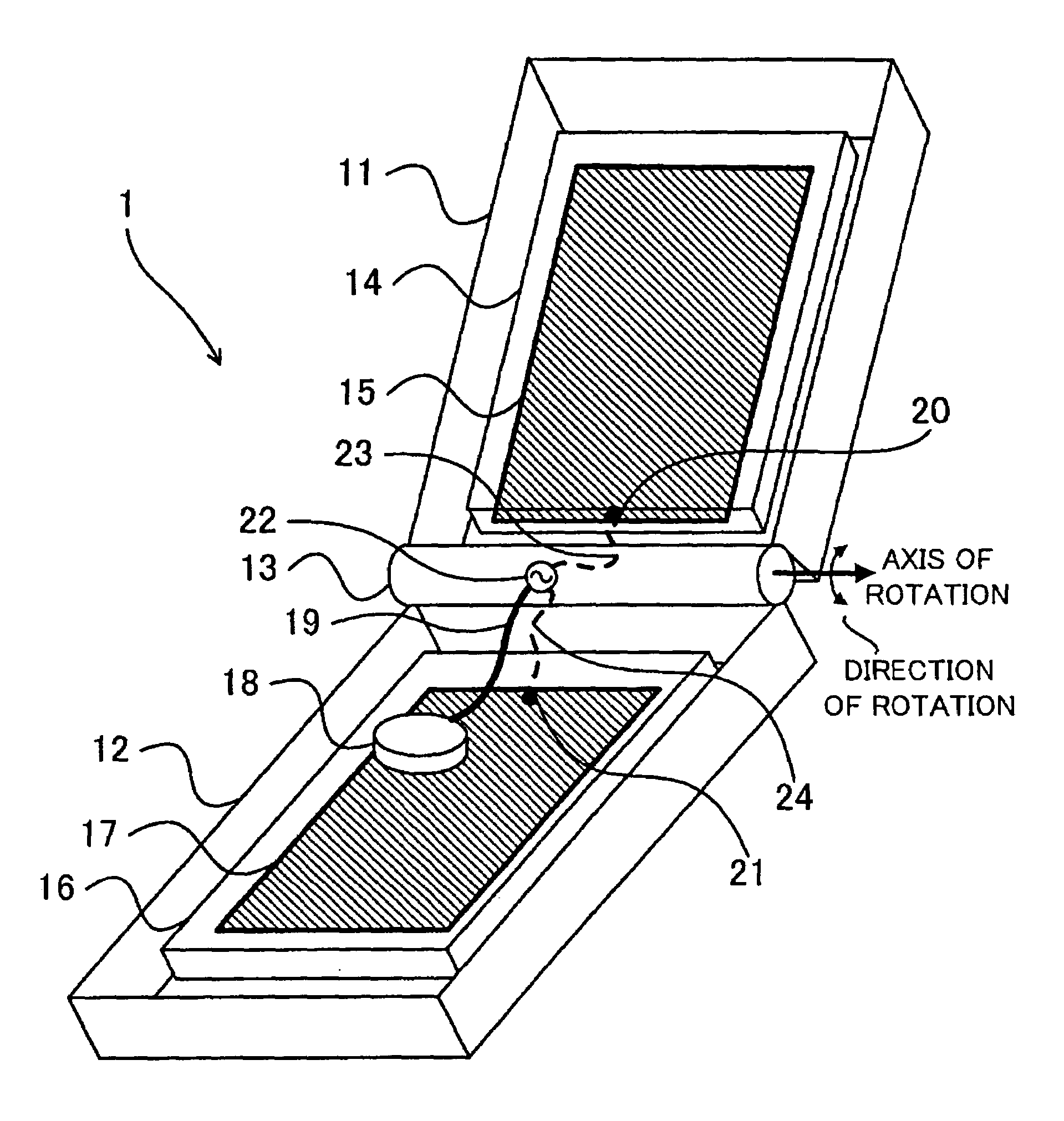
[0051] described above, the cases of the radio apparatus 1 may be made thinner and its antenna frequency range may be made broader than conventional ones by using the PCB ground patterns as the antenna elements. The shape of the connections from / to the feeding point may not be affected much by opening or closing the cases so that the antenna characteristic is stable.

[0052]A second embodiment of the present invention will be described with reference to FIG. 5 and FIG. 6. A radio apparatus in the second embodiment adopts a same configuration as the configuration of the radio apparatus 1 in the first embodiment shown in FIG. 1 that is referred to as necessary, except for connections around the feeding point 22.

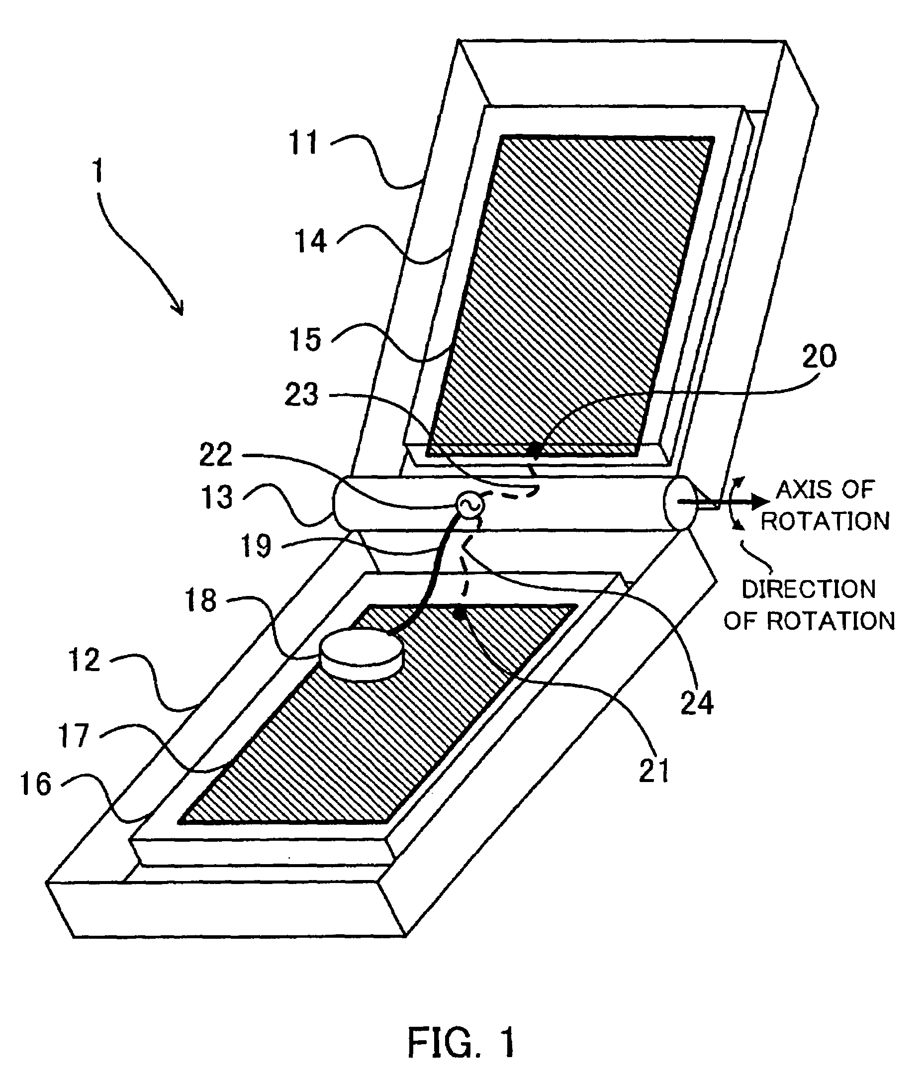
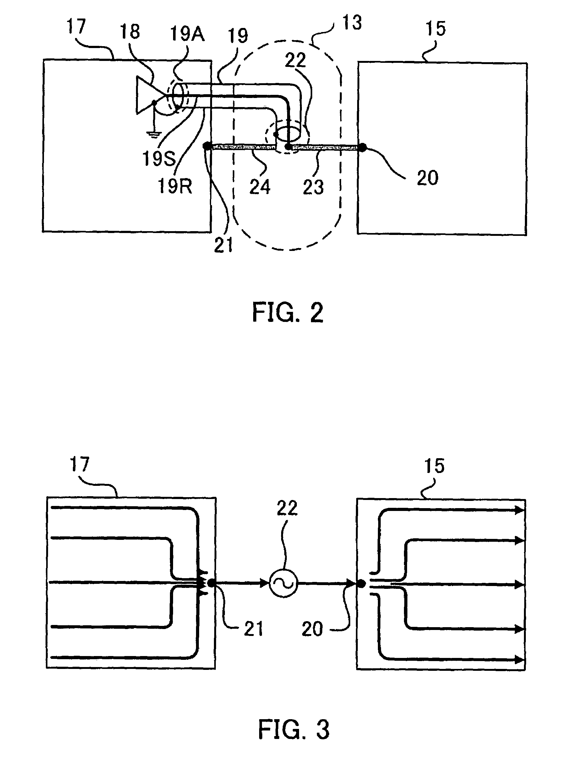
[0053]FIG. 5 is a schematic diagram of an example of such connections. Each of portions given the reference numeral 13, 15, 17 through 19, 19A / 19S / 19R or 20 through 22 is a same as the corresponding one shown in FIG. 2, and its explanation is omitted. In FIG. 5, shown is a flexib...

second embodiment

[0056]FIG. 6 is a schematic diagram of another example of connections around the feeding point 22 in the Each of portions given the reference numeral 13, 15, 17, 18 or 20 through 22 is a same as the corresponding one shown in FIG. 2, and its explanation is omitted. In FIG. 6, shown is a flexible PCB 26 to connect the first PCB 14 (not shown) and the second PCB 16 (not shown) through the hinge part 13.

[0057]The flexible PCB 26 has a first printed pattern 26a to connect the first antenna element 15 and the feeding point 22 for a signal connection, and has a second printed pattern 26b to connect the second antenna element 17 and the feeding point 22 for a return connection.

[0058]The flexible PCB 26 includes a microstrip line 27 formed as a printed pattern and connected to the radio circuit 18 at an end thereof, and the other end of the microstrip line 27 is the feeding point 22. The microstrip line 27 includes a signal line and a return line.

[0059]The signal line of the microstrip lin...

third embodiment

[0065]FIG. 8 is a schematic diagram of another example of the connections around the feeding point 22 in the Each of portions given the reference numeral 13, 15, 17, 18, 19, 19A / 19S / 19R or 20 through 22 is a same as the corresponding one shown in FIG. 2, and its explanation is omitted. In FIG. 8, shown is a flexible PCB 29 to connect the first PCB 14 (not shown) and the second PCB 16 (not shown) through the hinge part 13.

[0066]The signal line 19S is connected to a printed pattern 29a of the flexible PCB 29 at the feeding point 22, and the printed pattern 29a is connected to the first antenna element 15 at the first connecting spot 20. The return line 19R is directly connected to the second antenna element 17 at the second connecting spot 21. In FIG. 8, the first antenna element 15 and the second antenna element 17 form an antenna equivalent to the antenna similarly formed in FIG. 7, while making use of a flexible PCB that is generally used in radio apparatus configurations with two...


PUM


Abstract

There is provided a radio apparatus having a built-in type antenna of a broad frequency range in a thin case. The radio apparatus comprises a fist case containing a first printed circuit board (PCB) and a second case containing a second PCB. The two cases are joined by a hinge part. A radio circuit is contained in the first or the second case or the hinge part, and is connected to a first end of a feeder line including a signal line and a return line. A first antenna element formed as a printed pattern of the first PCB is connected, by a first conductor, to the signal line at a feeding point, i.e., a second end of the feeder line. A second antenna element formed as a printed pattern of the second PCB is connected, by a second conductor, to the return line at the feeding point.

Description

CROSS REFERENCE TO RELATED APPLICATIONS[0001]This application is based upon and claims the benefit of priority from the prior Japanese Patent Application No. 2004-270256 filed on Sep. 16, 2004; the entire contents of which are incorporated herein by reference.FIELD OF THE INVENTION[0002]The present invention relates to a radio apparatus having an antenna.DESCRIPTION OF THE BACKGROUND[0003]More and more radio apparatuses like mobile phones are used for various applications as radio communication technologies remarkably grow these days. A recent trend to be noted is a radio apparatus of multiple uses, i.e., ordinary voice and data communications plus receiving digital TV broadcasting or short-range radio links. Such a radio apparatus is required to have a broader frequency range than conventional ones, and this trend is pushed forward by developing ultra-wide-band (UWB) technologies.[0004]Broadening a frequency range of a radio apparatus needs broadening a frequency range of each comp...

Claims


Application Information

Patent Timeline
Patent Type & Authority Patents(United States)
IPC IPC(8): H01Q1/24H04B1/38
CPCH01Q1/084H04B1/3833H01Q21/28H01Q1/243
Inventor MINEMURA, TAKASHI
Owner GK BRIDGE 1
Why Eureka
Try Eureka