Vibrationally decoupling gasket

a gasket and vibration isolation technology, applied in the field of fluid seals, can solve the problems of poor vibration isolation, poor noise, vibration and harshness (nvh) isolation characteristics between the two members, and poor vibration isolation effectiveness of one member from the other, so as to avoid the effect of high compressive loading, effective sealing, and high compressive loading

Inactive Publication Date: 2006-02-07
FREUDENBERG NOK GEN PARTNERSHIP
View PDF32 Cites 32 Cited by
  • Summary
  • Abstract
  • Description
  • Claims
  • Application Information

AI Technical Summary

Benefits of technology

[0008]An advantage of the present invention is that effective sealing is achieved between two members while providing for vibrational isolation between the two members.
[0009]Another advantage of the present invention is that a surface of each member can be sealed independently of the surface on the other member, with a membrane sealingly connected between the sealing surface of each member. This allows for effective sealing without requiring high compressive loading between surfaces of the members. By avoiding the high compressive loading, the gasket provides for good vibrational isolation between the members.
[0010]A further advantage of the present invention is that the number of fasteners can be reduced since balancing of the gasket compressive sealing load is significantly reduced. For example, the number of fasteners used to fasten an oil pan to an engine block can be reduced.

Problems solved by technology

However, while producing an effective seal, these highly compressed gaskets can become a medium for transmitting vibrations, creating poor noise, vibration and harshness (NVH) isolation characteristics between the two members.
All of these conventional gaskets require a high compressive sealing load to assure an effective seal between the members, so the effectiveness of vibrational isolation of one member from the other is poor.
For effective sealing with the RTV, however, it requires a hard mount between the members, which also provides poor vibration isolation.

Method used


Image

  • Vibrationally decoupling gasket
  • Vibrationally decoupling gasket
  • Vibrationally decoupling gasket

Examples


first embodiment

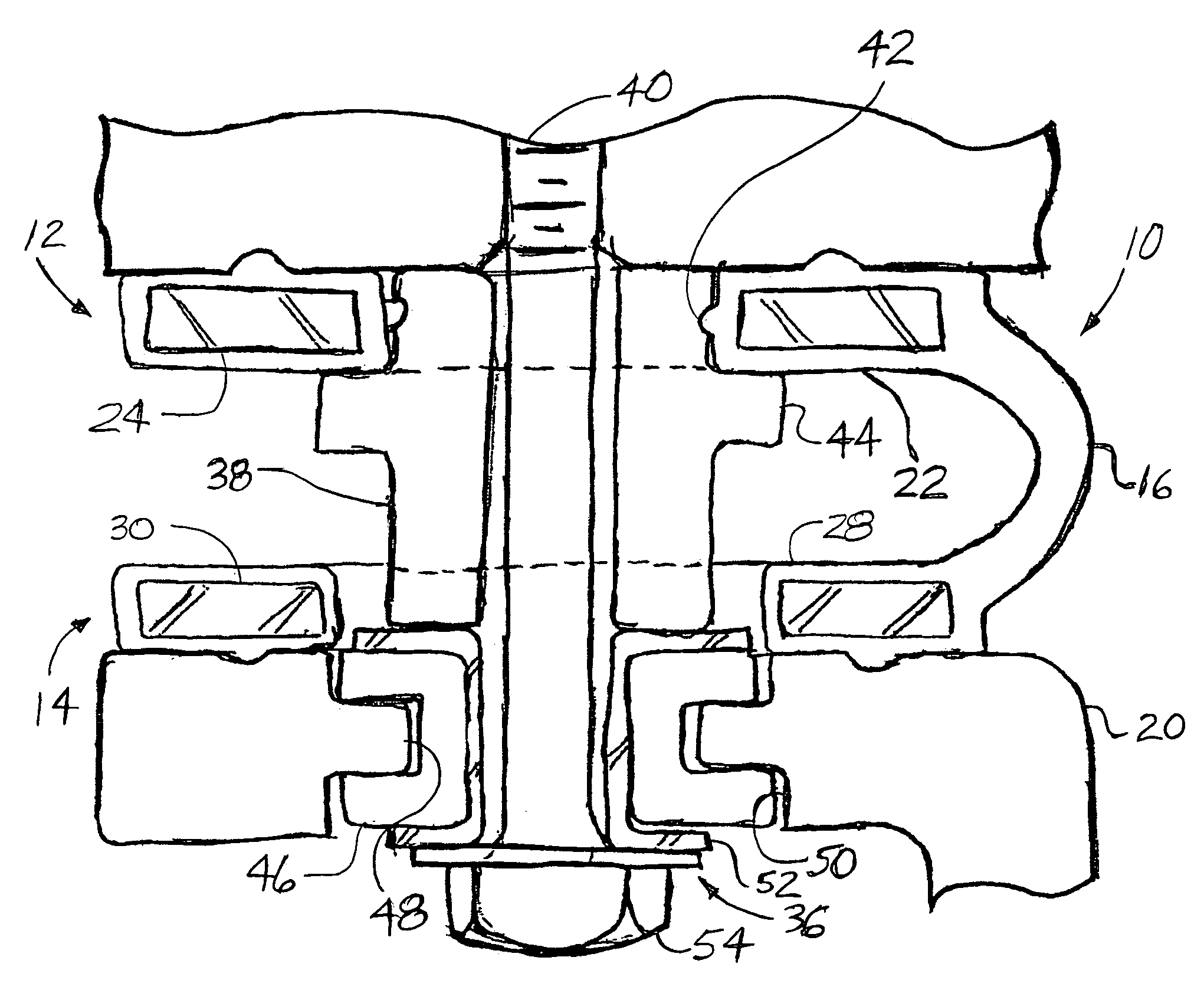
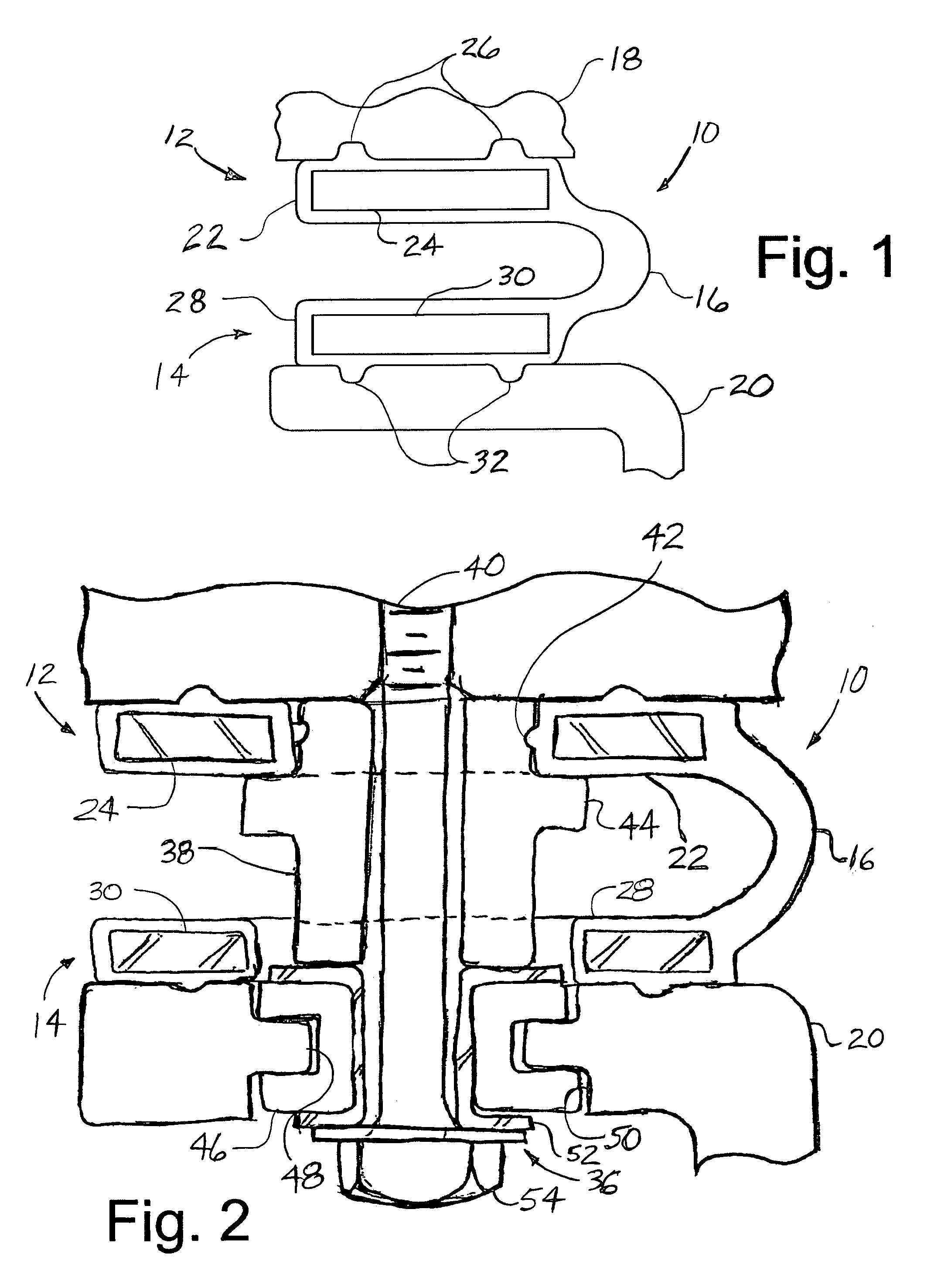
[0023]FIGS. 1 and 2 illustrate the present invention. A gasket 10 is shown that includes a first sealing portion 12, a second sealing portion 14, and an elastic arm 16 extending between the first portion 12 and the second portion 14. The first sealing portion 12 is in sealing engagement with a first member 18, while the second sealing portion 14 is in sealing engagement with a second member 20. The first member 18 and second member 20 may be, for example, an engine block and an oil pan, or a rocker / cam cover and an engine block—although, the gasket 10 of the present invention may be used to seal between other types of components where a fluid is sealed in (or out) and a reduction in vibration transmission between two components is desired. In FIGS. 1 and 2, if the first member 18 is an engine block and the second member 20 is an oil pan, then the oil side is preferably to the right as seen in FIGS. 1 and 2, with the atmosphere side to the left.

[0024]The first sealing portion 12 incl...

fifth embodiment

[0037]FIG. 8 illustrates a seventh preferred embodiment of a gasket 610 according to this invention. Elements in this embodiment that are similar to elements in the previous embodiments will be similarly designated, but with 600-series numbers. A second sealing portion 614 is similar to the second sealing portion in the present invention, with a generally U-shaped flange 630 creating a sealing and retaining force for sealing ribs 632 abutting a flange 662 of a second member 620. The first sealing portion 612 is now shaped similar to an O-ring and fits into a recess 668, with an interference fit between the two in order to create a sealing and retaining force between them. Again, the first seal portion 612 forms a seal against the first member 618 without requiring any compressive force contributed by the second member 620. An elastic arm 616 extends between and is preferably formed integral with the first and second sealing portions 612, 614. As with the previous embodiments, the ga...

ninth embodiment

[0040]FIG. 11 illustrates a tenth preferred embodiment of a gasket 910 according to this invention. Elements in this embodiment that are similar to elements in the previous embodiments will be similarly designated, but with 900-series numbers. The first and second sealing portions 912, 914 are essentially the same as in the ninth embodiment, but the elastic arm 916 is longer.

[0041]FIG. 12 illustrates an eleventh preferred embodiment of a gasket 1010 according to this invention. Elements in this embodiment that are similar to elements in the previous embodiments will be similarly designated, but with 1000-series numbers. A first sealing portion 1012 has a pair of sealing extensions 1026 that fit into a corresponding pair of recesses 1068 in the first member 1018. A second sealing portion 1014 has a pair of sealing extensions 1032 that fit into a corresponding pair of recesses 1070, with a membrane extending between the first and second sealing portions 1012, 1014. This gasket 1010 al...


PUM


Abstract

A gasket includes a fist sealing portion, a second sealing portion, and an elastic arm sealingly connecting between the two. The first sealing portion sealingly engages a first member and the second sealing portion sealingly engages a second member. The elastic arm is not highly compressed between the members, allowing the gasket to vibrationally decouple the first member from the second member.

Description

CROSS REFERENCE TO RELATED APPLICATIONS[0001]This clams the benefit of U.S. provisional patent application identified as Application No. 60 / 349,024, filed Jan. 15, 2002.BACKGROUND OF INVENTION[0002]This invention relates in general to fluid seals. More specifically, this invention relates to gaskets that connect two sealing portions, which prevent fluid leakage between the two, while reducing the transmission of vibrations through the gasket.[0003]In general, conventional gaskets require a relatively high compressive load between the members being sealed in order for the gasket to provide an effective seal. For example, a gasket placed between two stationary members, such as an engine block and an oil pan, or an engine cylinder head and a valve / cam cover, is compressed between these elements. However, while producing an effective seal, these highly compressed gaskets can become a medium for transmitting vibrations, creating poor noise, vibration and harshness (NVH) isolation charact...

Claims


Application Information

Patent Timeline
Patent Type & Authority Patents(United States)
IPC IPC(8): F02F11/00F16J15/02F16J15/06F16J15/32
CPCF16J15/024F16J15/3224F16J15/064Y10S277/916
Inventor SAKATA, DAVID
Owner FREUDENBERG NOK GEN PARTNERSHIP
Why Eureka
Try Eureka