Optical fiber cutting apparatus

A technology of cutters and fibers, applied in the directions of instruments, light guides, optics, etc., can solve the trouble of properly storing various gaskets, the time-consuming cutters, etc., and achieve satisfactory reproducibility.

Active Publication Date: 2008-07-16
SUMITOMO ELECTRIC IND LTD
View PDF8 Cites 0 Cited by
  • Summary
  • Abstract
  • Description
  • Claims
  • Application Information

AI Technical Summary

Problems solved by technology

Distance adjustment parts such as shims are small, and setting work in the cutter tends to take time
Also, it may be necessary to prepare more than one kind of spacer according to the various lengths in which the optical fiber protrudes from the holder, and proper storage of multiple kinds of spacers is troublesome

Method used


Image

  • Optical fiber cutting apparatus
  • Optical fiber cutting apparatus
  • Optical fiber cutting apparatus

Examples


Embodiment Construction

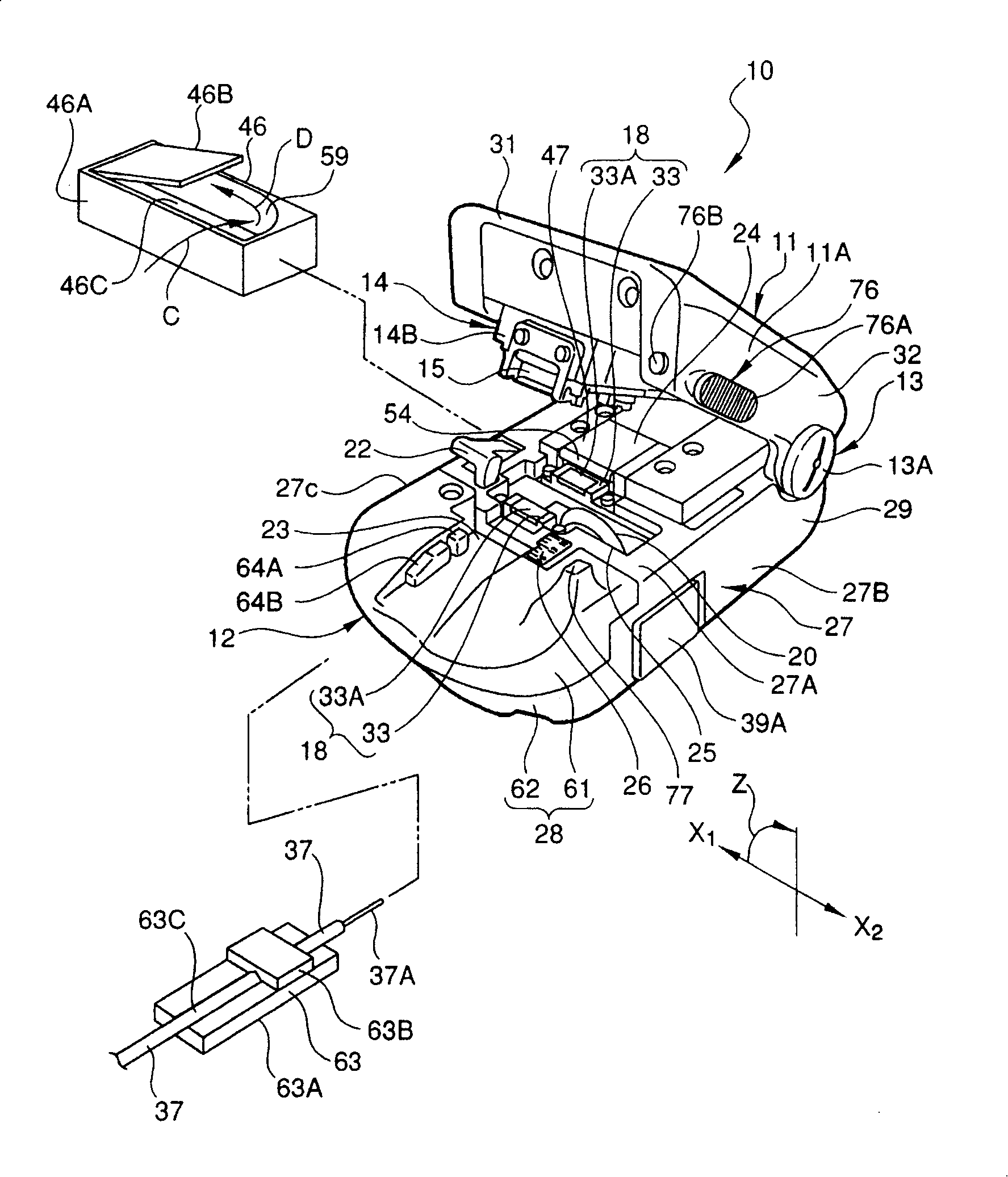
[0043] Embodiments of the present invention will be described below with reference to the accompanying drawings. The drawings are provided for the purpose of explanation only and do not limit the scope of the invention. The same symbols denote the same parts in the drawings to avoid repeated explanations. The dimensional ratios in the drawings are not always accurate.

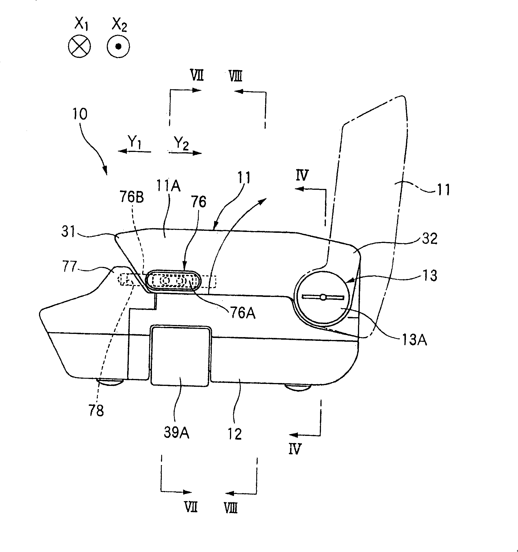
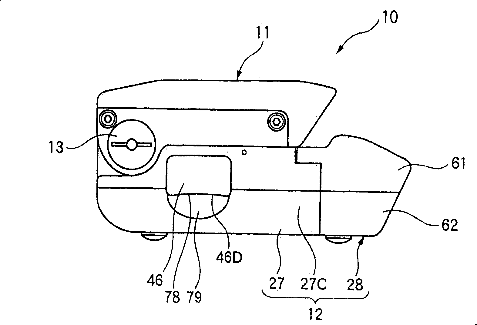
[0044] figure 1 is a perspective view of a fiber cutter and a holder to be mounted thereon according to a first embodiment of the present invention. figure 2 , 3 , and 4 are a right side view, a left side view, and a rear view, respectively, of the fiber cutter according to the first embodiment of the present invention. 5 is a sectional view of the fiber cutter according to the first embodiment of the present invention, and shows a state in which upper and lower housings are opened. Fig. 6 is a view similar to Fig. 5, and shows a state in which upper and lower cases are closed. 7, 8, and 9 are cross-sec...


PUM


Abstract

A fiber cleaver is provided which is capable of cleaving a glass fiber portion in a short time without depending on a particular working environment. The fiber cleaver comprises a holding member for holding a glass fiber portion of an optical fiber, a cutter for affording a scratch to the glass fiber portion which is held by the holding member, an elastic member or spring for moving the cutter, and a slider engaging member for maintaining the elastic member or spring in a state of elastic deformation. Also provided is a fiber cleaver comprising a holding member for holding the glass fiber portion of an optical connector, a cutter for affording a scratch to the glass fiber portion held by the holding member, and a holder engaging part for holding a holder that holds an optical fiber at its part having a protective covering. The holder engaging part has a first holder engaging member for pushing and holding the holder in a direction parallel to a movement direction of the cutter.

Description

technical field [0001] The present invention relates to a fiber cutter capable of cutting the glass fiber portion of an optical fiber to a desired length. Background technique [0002] In recent years, the demand for large-capacity and high-speed information transmission has increased, and optical fiber communication networks have been installed in office buildings and general homes. In the case of pulling an optical fiber from a main line into a home, for example, the optical fiber on the side of the main line and the optical fiber in the home must be spliced. The optical fibers are spliced ​​together by first exposing the glass fiber portions by removing the sheaths of the respective optical fibers; cutting the exposed glass fiber portions; and butting the cut end faces of the glass fiber portions to each other, thereby being spliced ​​together. [0003] In the fiber cutters disclosed in Japanese Patent Application Publication No. Tokukai 2003-165740 and Japanese Patent A...

Claims


Application Information

Patent Timeline
Patent Type & Authority Patents(China)
IPC IPC(8): G02B6/00
Inventor 本间敏彦
Owner SUMITOMO ELECTRIC IND LTD
Why Eureka
Try Eureka