
Microelectronic substrate with integrated devices and its manufacturing method

A technology of microelectronics, microelectronic devices, applied in the field of manufactured devices, which can solve the problems of increasing component size, speed and performance degradation, long conductive traces, etc.

Inactive Publication Date: 2008-07-16
INTEL CORP
View PDF1 Cites 0 Cited by
  • Summary
  • Abstract
  • Description
  • Claims
  • Application Information

AI Technical Summary

Problems solved by technology

However, single-sided board 200 results in relatively long conductive traces 204, which in turn degrades speed and performance
Single panel 200 also requires a larger surface area for the routing of conductive traces 204 to interconnect multiple microelectronic devices 208, which increases the size of the resulting assembly

Method used


Image

  • Microelectronic substrate with integrated devices and its manufacturing method
  • Microelectronic substrate with integrated devices and its manufacturing method
  • Microelectronic substrate with integrated devices and its manufacturing method

Examples


Embodiment Construction

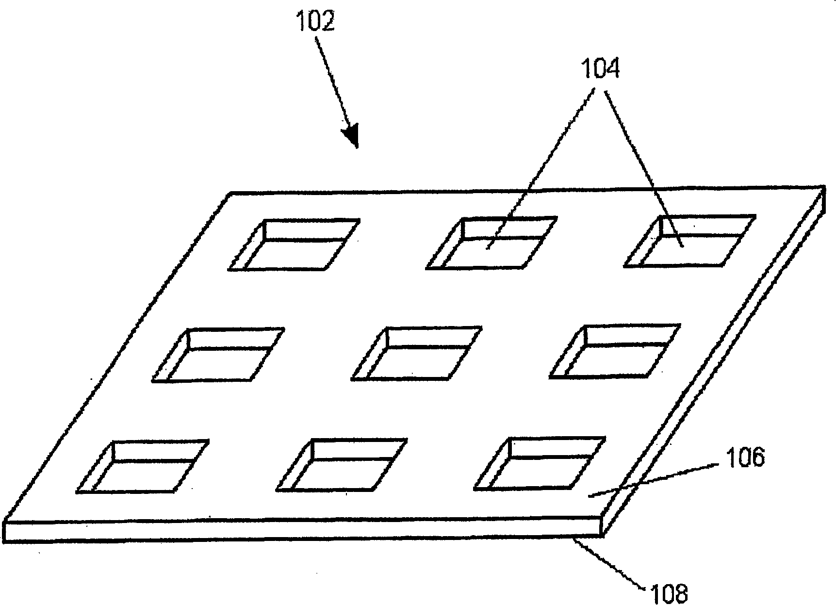
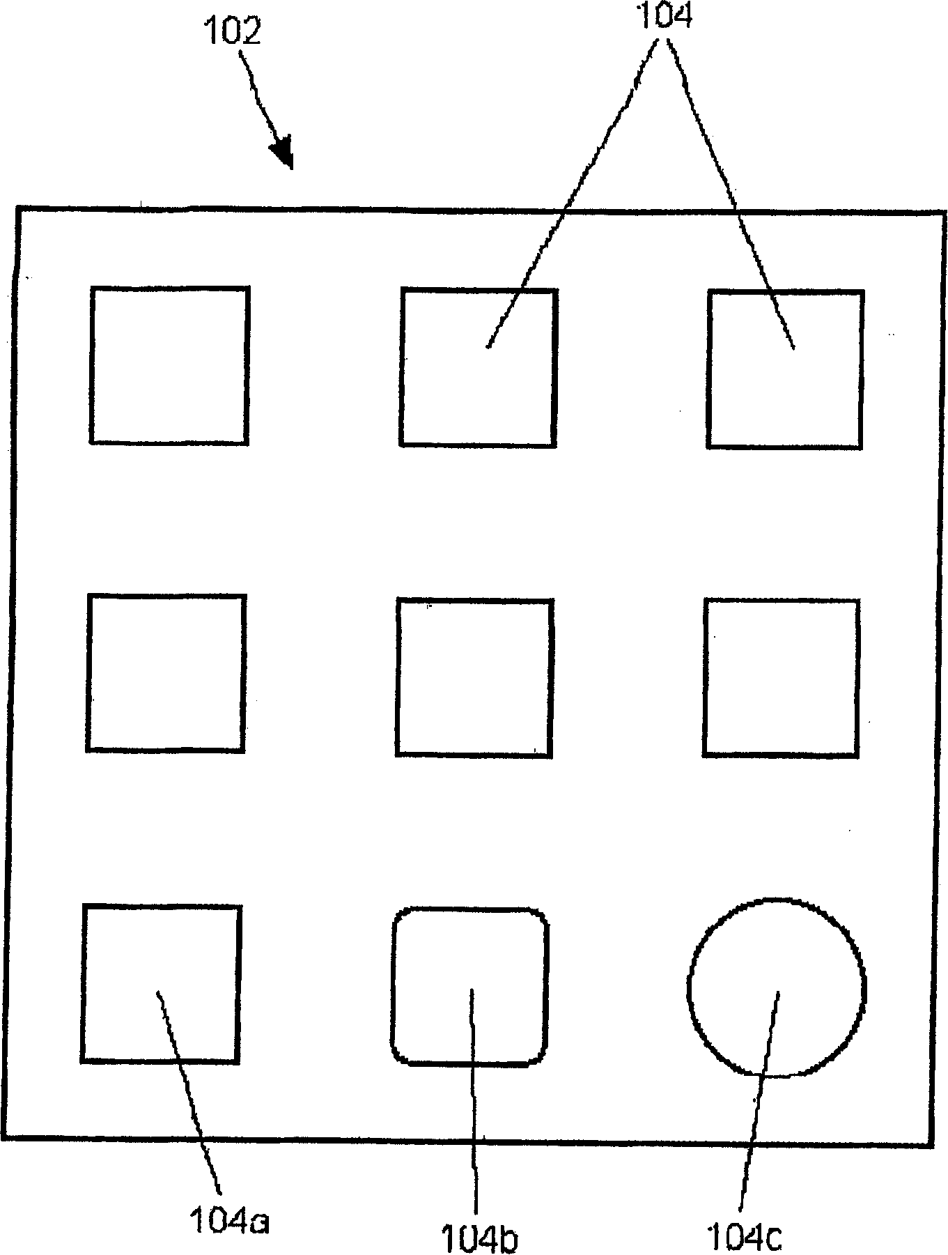
[0025] Although Figures 1 to 19 Various views of the present invention are shown, however these figures are not meant to represent a precise and detailed depiction of the microelectronic assembly. Rather, the figures merely show microelectronic assemblies in a manner that more clearly conveys the concepts of the invention. In addition, elements common to these figures are denoted by the same reference numerals.

[0026] The present invention includes a substrate fabrication technique that places at least one microelectronic die within at least one opening of a microelectronic substrate core and secures the microelectronic die within said opening with an encapsulant, or at least one The microelectronic die is encapsulated within the encapsulant without the core of the microelectronic substrate. An interconnect layer of dielectric material and conductive traces is then fabricated over the microelectronic die, encapsulation material, and microelectronic substrate core (if any)...


PUM


Abstract

A microelectronic substrate including at least one microelectronic die disposed within an opening in a microelectronic substrate core, wherein an encapsulation material is disposed within portions of the opening not occupied by the microelectronic dice, or a plurality microelectronic dice encapsulated without the microelectronic substrate core. Interconnection layers of dielectric materials and conductive traces are then fabricated on the microelectronic die, the encapsulation material, and the microelectronic substrate core (if present) to form the microelectronic substrate.

Description

technical field [0001] This application is a continuation-in-part of Application No. 09 / 640961, filed August 16,2000. [0002] The present invention relates to an apparatus and process for the manufacture of microelectronic substrates. In particular, the present invention relates to a fabrication technique by which at least one microelectronic die may be encapsulated within a microelectronic substrate core or at least one microelectronic die (without the microelectronic substrate core) to form a microelectronic substrate. Background technique [0003] The substrate connecting the individual microelectronic devices is present in virtually all newly manufactured electronic devices. These substrates are usually printed circuit boards. A printed circuit board is basically a dielectric substrate with metal traces formed in or on the dielectric substrate. One type of printed circuit board is single-sided. As shown in FIG. 20 , the single-sided board 200 includes a dielectric s...

Claims


Application Information

Patent Timeline
Patent Type & Authority Patents(China)
IPC IPC(8): H01L23/538H01L21/48H01L23/12H01L21/56H01L21/60H01L21/68H01L23/31H01L25/04H01L25/18H05K1/18H05K3/46
CPCH01L2924/18162H01L2224/20H01L2924/15174H01L2924/19043H01L24/96H01L2224/04105H01L2224/16H01L21/568H01L2924/01033H01L2924/19042H01L2924/01006H01L2924/15311H01L24/19H01L2924/01029H01L2924/01078H01L2924/19041H01L2924/01013H01L23/5389H01L2224/12105H01L2224/0401H01L2224/16225H01L2224/24137H01L2924/12042H01L2224/18H01L21/56H01L21/561H01L23/3114H01L24/97H01L2224/19H01L2224/211H01L2224/97H01L2924/15192H01L2924/15331H05K1/185H05K3/4602H01L2924/351H01L2224/96H01L2924/00H01L2224/82H01L2924/00012H01L23/538
Inventor J·李Q·邬S·托勒
Owner INTEL CORP
Learn More