Double-end inserting elastic meshing body pile connecting end plate and prefab

A plug-in and elastic technology, which is applied in the field of double-head plug-in elastic meshing body pile-connecting end plates, can solve the problems of slow butt-connecting piles, complicated manufacturing molds and processes, and high processing costs, and achieve fast butt-connecting piles and work. The effect of high efficiency and low cost

Inactive Publication Date: 2008-08-06
周兆弟
View PDF4 Cites 0 Cited by
  • Summary
  • Abstract
  • Description
  • Claims
  • Application Information

AI Technical Summary

Problems solved by technology

The fly in the ointment is: first, before docking, the expansion screw needs to be screwed into the screw thread of the expansion nut, and then the butt connection can be realized, so the speed of butt connection is slow; The structure is different, so its manufacturing mold and process are complicated, and the processing cost is high

Method used


Image

  • Double-end inserting elastic meshing body pile connecting end plate and prefab
  • Double-end inserting elastic meshing body pile connecting end plate and prefab
  • Double-end inserting elastic meshing body pile connecting end plate and prefab

Examples


Embodiment 1

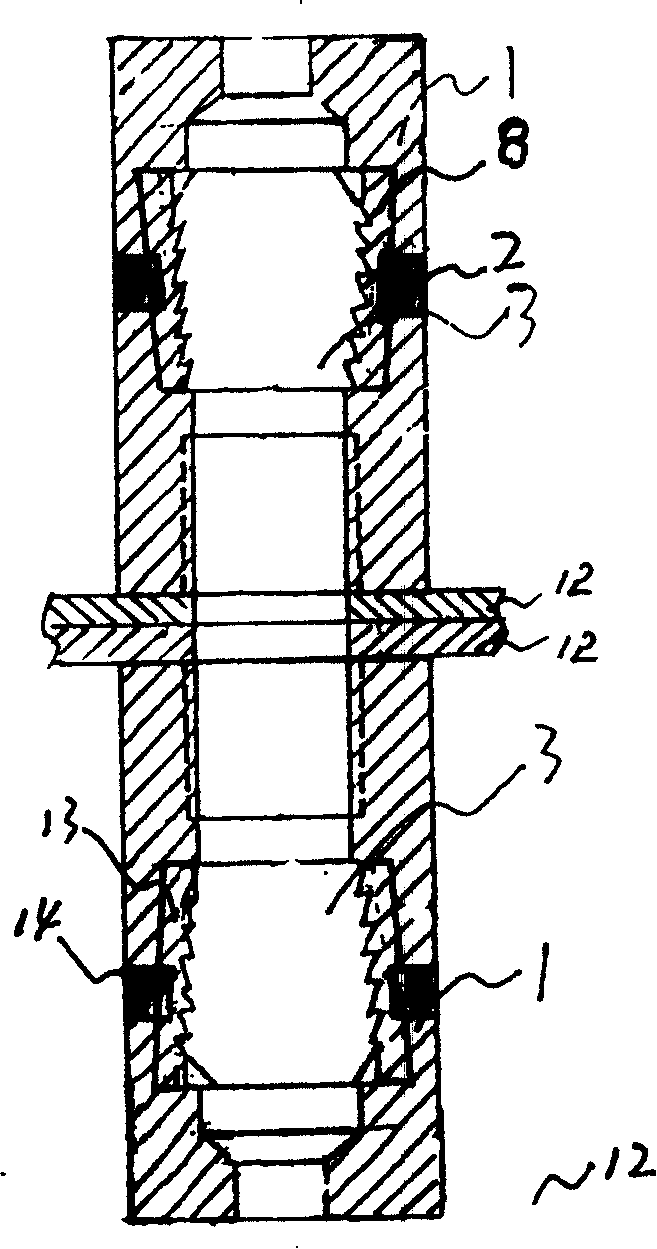
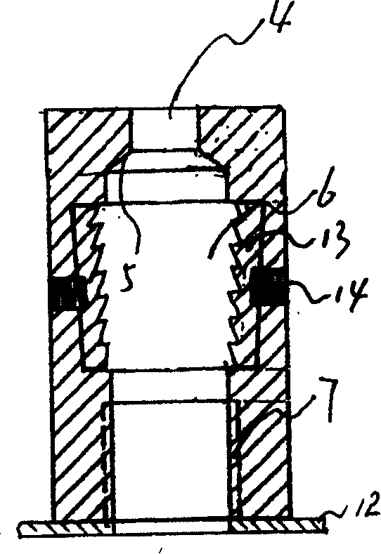
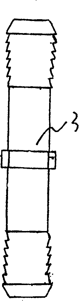
[0017] Embodiment 1: with reference to attached Figure 1~5 . The double-ended plug-in elastic meshing body piling end plate includes an end plate 12, two or more expansion nuts 1 are distributed on the end plate 12, and the plug-in meshing tooth sleeve 8 is located In the cavity 6, a spring 2 is placed between the outside of the plug-in meshing gear sleeve 8 and the wall of the expansion nut 1, generally a compression spring is used, and one end of the compression spring 2 is located in the hole in the wall of the expansion nut 1 and connected to the wall of the expansion nut 1. The rivet at the end of the hole touches, and the other end touches the outer side of the plug-in gear sleeve. When docking, the double-headed gear body 3 is inserted into the 8 plug-in gear sleeves and under the action of the spring 2, the double-headed gear body 3 Mesh with the plug-in toothed sleeve 8, see attached figure 1 . Tension nut 1 adopts metal (as steel, stainless steel, alloy steel etc...

Embodiment 2

[0018] Embodiment 2: with reference to attached Figure 6 . On the basis of Embodiment 1, the prefabricated parts (pipe piles----circular tubular, square pipe piles, etc.) composed of double-ended plug-in elastic engagement body pile end plates, the two ends of the prefabricated part 10 are respectively equipped with The piling end plate 12 of the expansion nut 1, the headers 11 at the two ends of several longitudinal steel bars in the prefabricated part 10 are respectively clamped on the steel bar header clamping table 5 in the expansion nut 1, and the double-headed teeth engage 3 is used for the docking between two prefabricated parts 10. The double-end meshing tooth body 3 is elastically inserted into the plug-in meshing tooth sleeve 8 in the expansion nut 1 . (When the double-ended meshing tooth body 3 is docked with the pipe pile, the teeth at both ends of the double-ended meshing tooth body are elastically inserted into the plug-in meshing tooth sleeve in the expansion...

Embodiment 3

[0019] Embodiment 3: with reference to attached Figure 7 . On the basis of Examples 1 and 2, the pile connection structure between the pipe pile and the pipe pile, or between the bridge pier and the bridge pier, or between the utility pole and the utility pole, which is composed of a double-ended plug-in elastic engagement body pile connection end plate, needs to be docked The ends of the two prefabricated parts are respectively equipped with piling end plates with tension nuts, the opening of the tension nuts on the end plate of one prefabricated part and the tensioning nuts on the end plate of the other prefabricated part. The mouths of the nuts are facing each other, and the meshing teeth at both ends of the double-ended meshing teeth are respectively inserted into the plug-in meshing tooth sleeves in the expansion nut and form elastic engagement with the teeth in the plug-in meshing tooth sleeves to complete the gap between the prefabricated parts and the prefabricated pa...


PUM


Abstract

The invention relates to tubular interface, the pre-make part, which is made of pre-make part's interface and the connection instruction between the pre-make parts as well as the facture of the pre-make part. It comprises of end board, two or more inflation draw crew caps which distribute circumferentially on the end board. The insert-style mesh alveolus locates in the inflation cavity of the inflation draw screw cap and there is a spring sets between the outside of the alveolus and the wall of the inflation draw screw cap. When face-to-face connected, the double-edged mesh rack inserted in the insert-style mesh alveolus and spring meshes with the inner teeth of the insert-style mesh alveolus by the role of the spring. The pre-make part is made of the double-edged insert-style spring mesh connection board and it has connection stake end-board with the inflation draw screw caps at both the two ends. Many items of the portrait reinforcing steel bar's two ends clip to the steel cap of the inflation draw screw caps respectively. The double-edged mesh rack is used to the face-to-face connection of two pre-make parts.

Description

Technical field: [0001] The invention relates to a pipe pile joint, a prefabricated plate joint, a bridge pier joint, a bridge joint, an electric pole interface and its prefabricated parts, and a pipe pile joint, a prefabricated plate joint, a bridge pier joint and a bridge joint. The pipe pile and the connection between the pipe pile and the pipe pile, the connection between the prefabricated slab and the prefabricated slab, the connection between the bridge pier and the bridge pier, the connection structure between the prefabricated pole and the prefabricated pole and the production of prefabricated parts The method belongs to the fields of prefabricated part fastening and prefabricated part manufacturing. Background technique: [0002] This application is based on the applicant's patent application number 200410091063.9 and the name "upper screw and lower top connection pile buckle and prefabricated parts". It consists of an expansion nut, an expansion screw and a top ten...

Claims


Application Information

Patent Timeline
Patent Type & Authority Patents(China)
IPC IPC(8): E02D5/52E02D5/30E04B1/38
Inventor 周兆弟
Owner 周兆弟
Why Eureka
Try Eureka