Switching valve seal

一种环状密封、阀口的技术,应用在阀装置、阀的操作/释放装置、升阀等方向,能够解决增加泄露、分隔器泄露、压力波动等问题,达到节省成本、良好密封、低压力波动的效果

Inactive Publication Date: 2008-08-06
DUERR SYST GMBH
View PDF6 Cites 0 Cited by
  • Summary
  • Abstract
  • Description
  • Claims
  • Application Information

AI Technical Summary

Problems solved by technology

Leakage of raw process gas through the valve, allowing said gas to exit the device untreated, can significantly reduce the decomposition efficiency of the device
Additionally, conventional valve designs result in pressure fluctuations during switching that increase the likelihood of such leaks
[0006] Similar leak potential exists in traditional rotary valve systems
Additionally, such rotary valve systems typically include multiple internal dividers that leak over time and are expensive to manufacture and maintain

Method used


Image

  • Switching valve seal
  • Switching valve seal
  • Switching valve seal

Examples


Embodiment Construction

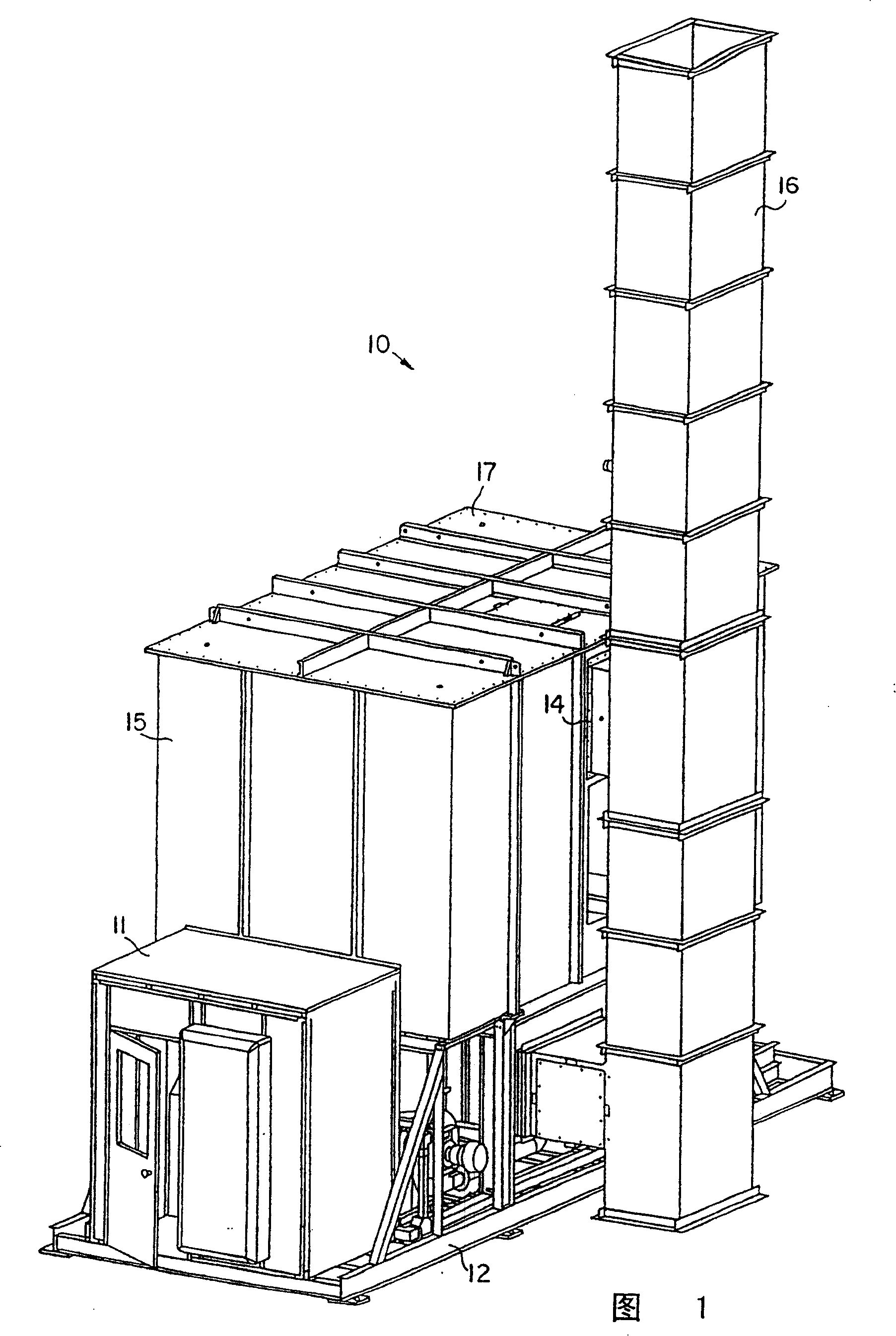
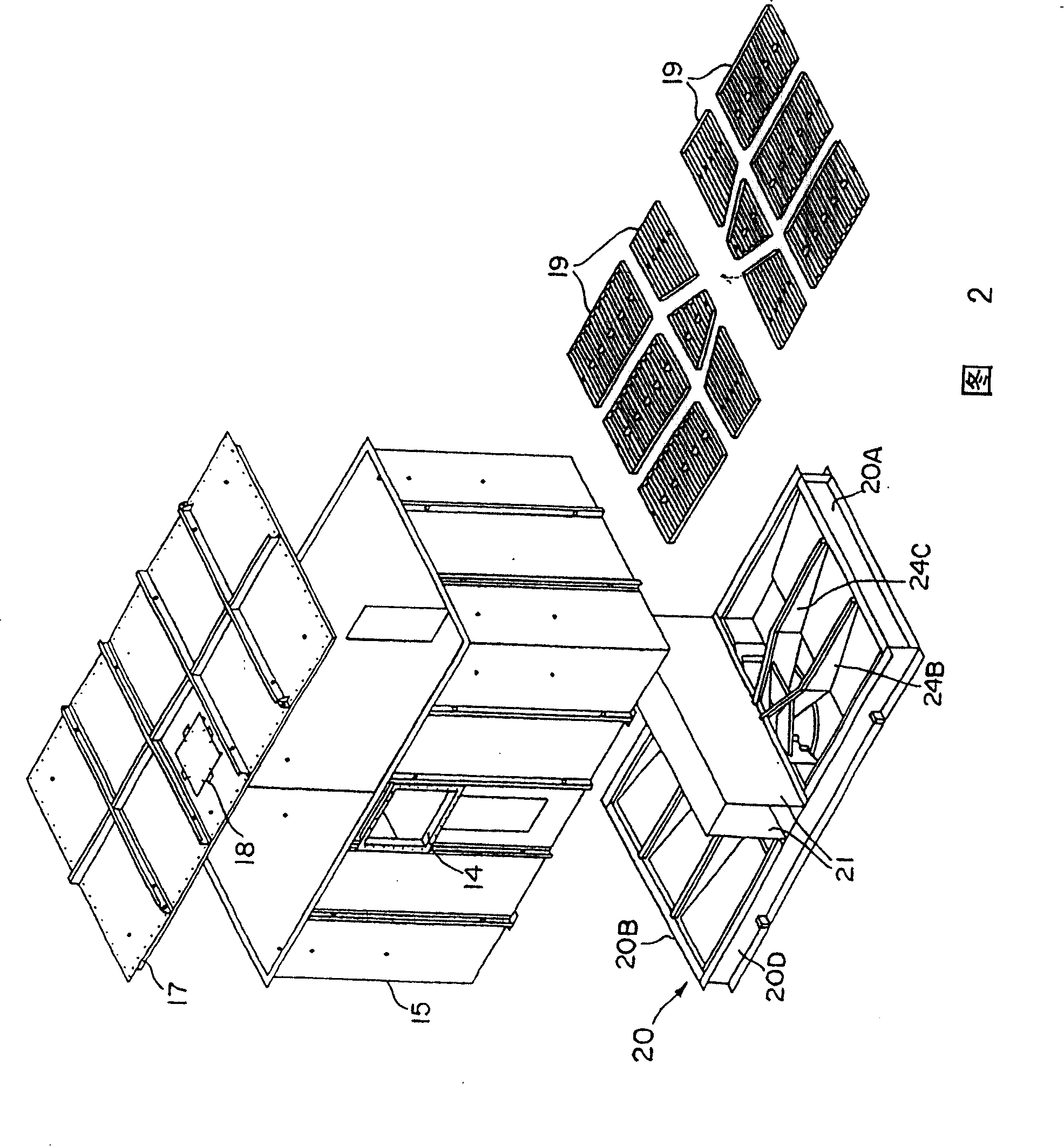
[0040]Referring first to Figures 1 and 2, a dual chamber regenerative thermal oxidizer 10 (catalytic or non-catalytic oxidizer) supported on a support 12 is shown. The oxidizer 10 includes an enclosure 15 within which are first and second heat exchange chambers in communication with a centrally mounted combustion zone to which a burner (not shown) can be connected and which can A combustion blower is supported on the frame 12 for supplying combustion air to the burner. The combustion zone includes a bypass outlet 14 in fluid communication with an exhaust stack 16 which is normally open to atmosphere. A control compartment 11 houses the controls for the device and is preferably also mounted on a stand 12 . Opposite the control chamber 11 is a fan (not shown) supported on a frame 12 to deliver process gas into the oxidizer 10 . Housing 15 includes an upper chamber or roof 17 having one or more access hatches 18 to allow operator access to housing 15 . Those skilled in the art...


PUM


Abstract

Switching valve utilizing a rotatable seal suitable for use in a regenerative thermal oxidizer (10), and oxidizer (10) including the switching valve (20). The valve (20) of the present invention exhibits excellent sealing characteristics and minimizes wear. The valve (20) has a seal plate (100) that defines two chambers, each chamber being a flow port (25) that leads to one of two regenerative beds of the oxidizer (10). The valve (20) also includes a switching flow distributor (50) that provides alternate channeling of the inlet or outlet process gas to each half of the seal plate. The valve operates between two modes: a stationary mode and a valve movement mode. In the stationary mode, a tight gas seal is used to minimize or prevent process gas leakage. The gas seal also seals during valve movement.

Description

technical field [0001] This invention relates to regenerative thermal oxidizers and switching valves. Background technique [0002] Regenerative thermal oxidizers are commonly used to decompose volatile organic compounds (VOC's) in high flow, low concentration emissions from industries and power plants. Said oxidizers generally require high oxidation temperatures in order to obtain high VOC decomposition. To achieve high heat recovery efficiency, the "dirty" process gas to be treated is preheated prior to oxidation. Typically, a heat exchange column is provided in order to preheat the gas. The column is usually filled with a heat exchange material that has good thermal and mechanical stability, and sufficient thermal mass. In operation, the process gas is sent through a preheated heat exchange column which heats the process gas to a temperature close to or at its VOC oxidation temperature. This preheated process gas is then directed into the combustion zone where any inc...

Claims


Application Information

Patent Timeline
Patent Type & Authority Patents(China)
IPC IPC(8): F23L15/02F27D17/00F16K3/06F16K1/00F16K31/53F23M20/00F27D99/00
CPCF27D17/008F23G7/068F27D2017/007F23L15/02F27D2099/0048Y10T137/5689F27D17/00Y02E20/34
Inventor J·T·卡什
Owner DUERR SYST GMBH
Why Eureka
Try Eureka