

Clamping device
A technology of clamping mechanism and connecting piece, applied in the direction of clamping, metal processing mechanical parts, support, etc., can solve problems such as poor positioning
- Summary
- Abstract
- Description
- Claims
- Application Information
AI Technical Summary
Problems solved by technology
Method used
Image

Examples
Embodiment Construction
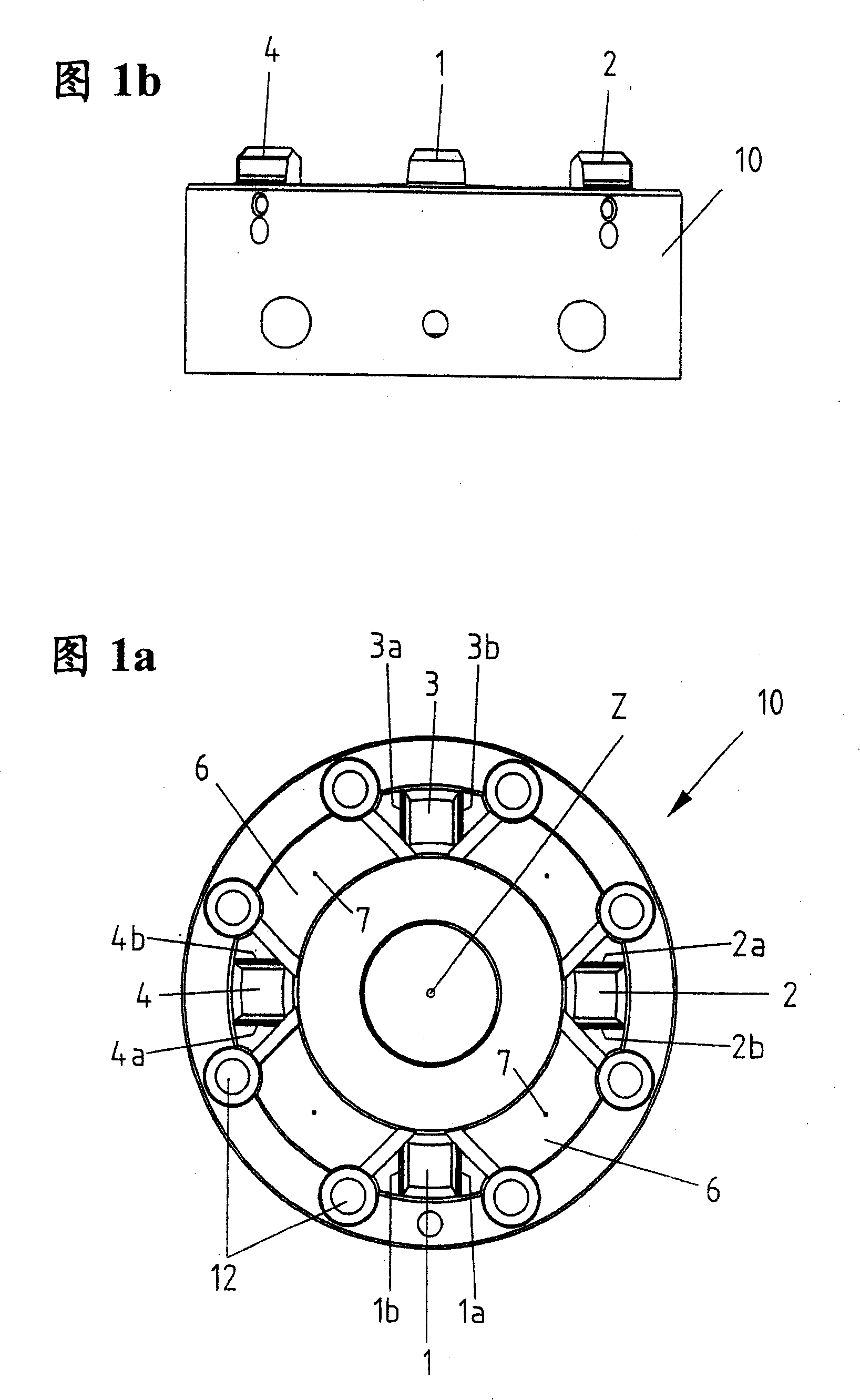
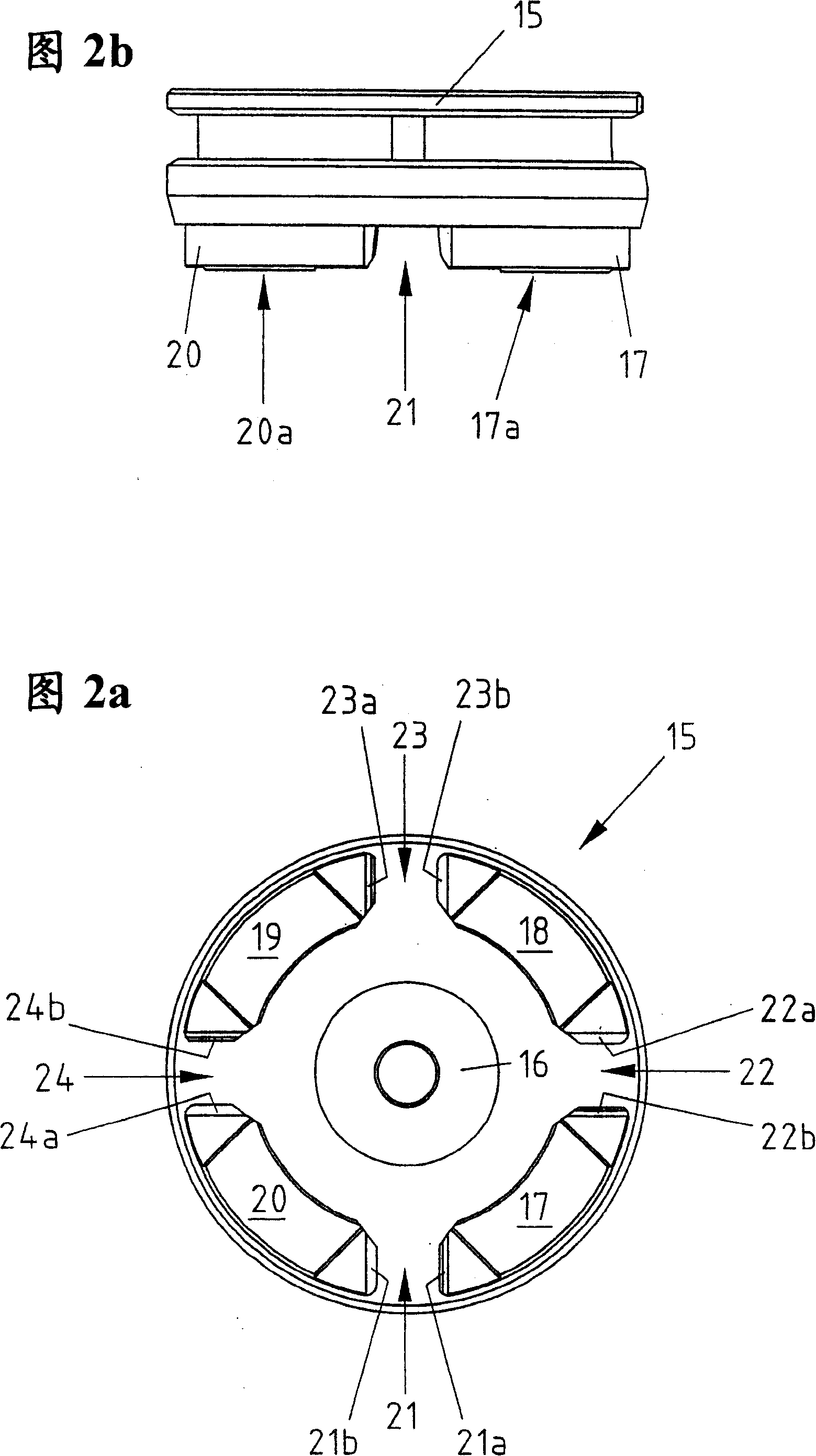
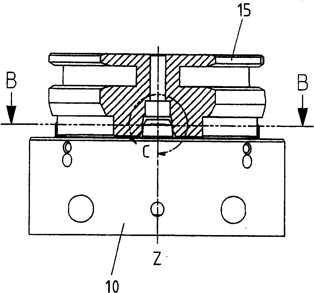
[0022] Figure 1a shows a top view of a first substantially cylindrical connecting element 10. Figure 1 b shows a side view of the first substantially cylindrical connecting element 10 . Typically, this first attachment 10 is connected to the machine tool and serves as a clamping member for a second attachment 15 as shown in Figures 2a and 2b, which can receive a workpiece, tool or similar.
[0023] On the top of the first connecting piece 10, four center pins 1, 2, 3, 4 protrude. These center pins are offset from each other by 90° with respect to the center line Z. Each central pin 1, 2, 3, 4 comprises two tapered sides 1a, 1b, 2a, 2b, 3a, 3b, 4a, 4b.
[0024] Between the two central pins 1, 2; 2, 3; 3, 4; 4, 1 there is an intermediate surface 6 which serves as a reference in the Z direction. In the middle of the surface 6, an outlet 7 is provided to allow the air to escape. For fixing, the first connecting piece 10 is provided with a plurality of fixing holes 12 .
[002...
PUM
 Abstract
Description
Claims
Application Information