Portalachse

A portal axle and axle technology, which is applied to vehicle components, control devices, transportation and packaging, etc., can solve the problems of increasing the diameter of the intermediate gear, the door distance cannot be further increased, and the spring support connection cannot be performed.

Active Publication Date: 2008-11-05
ZF FRIEDRICHSHAFEN AG
View PDF8 Cites 0 Cited by
  • Summary
  • Abstract
  • Description
  • Claims
  • Application Information

AI Technical Summary

Problems solved by technology

The distance between the axis of rotation of the drive pinion and the axis of rotation of the output spur gear cannot be increased further, because for this the diameter of the intermediate gear would need to be further increased, which would make it impossible to connect the spring bearings in the usual way

Method used


Image

  • Portalachse
  • Portalachse

Examples


Embodiment Construction

[0012] about figure 1 :

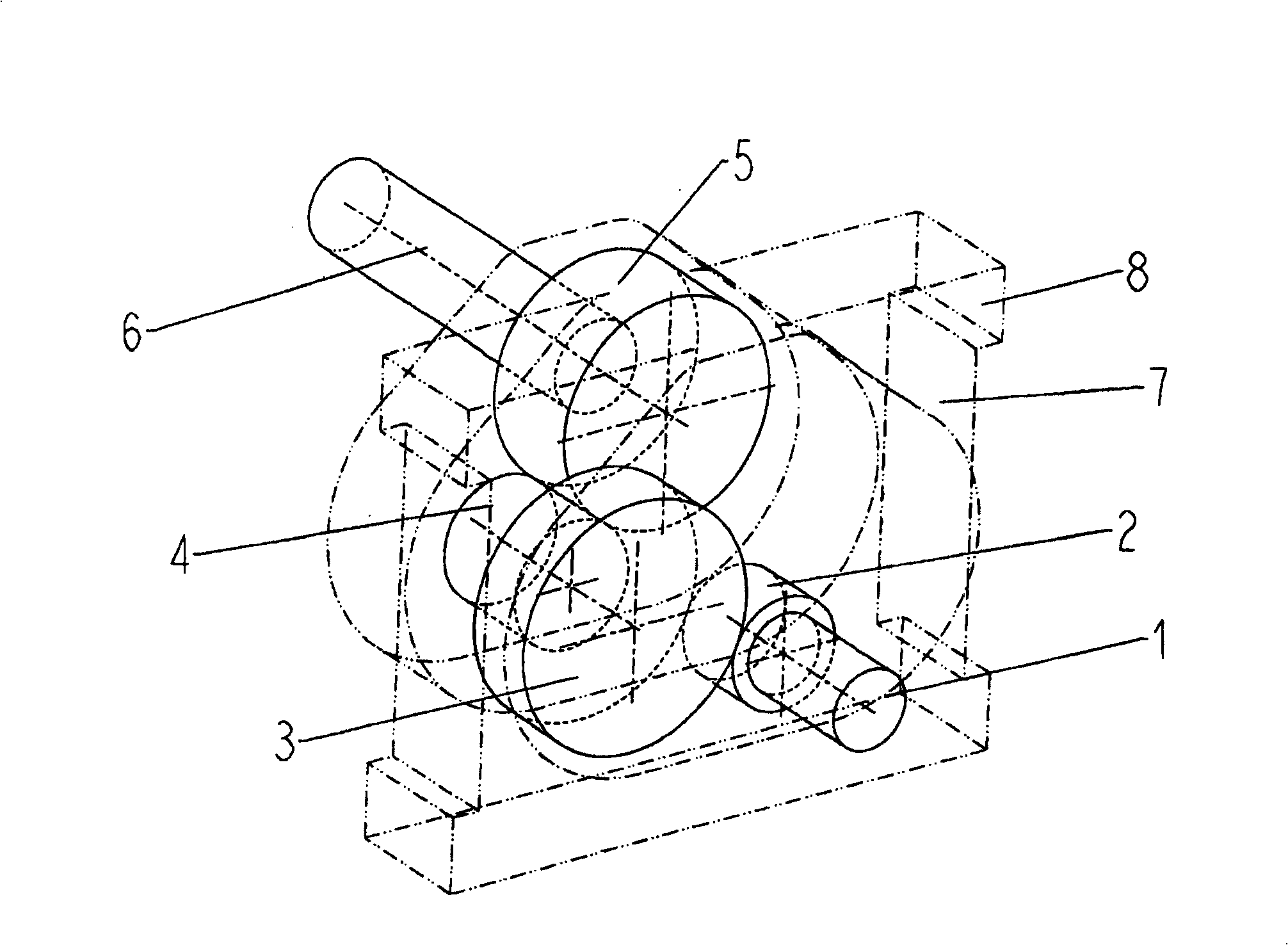
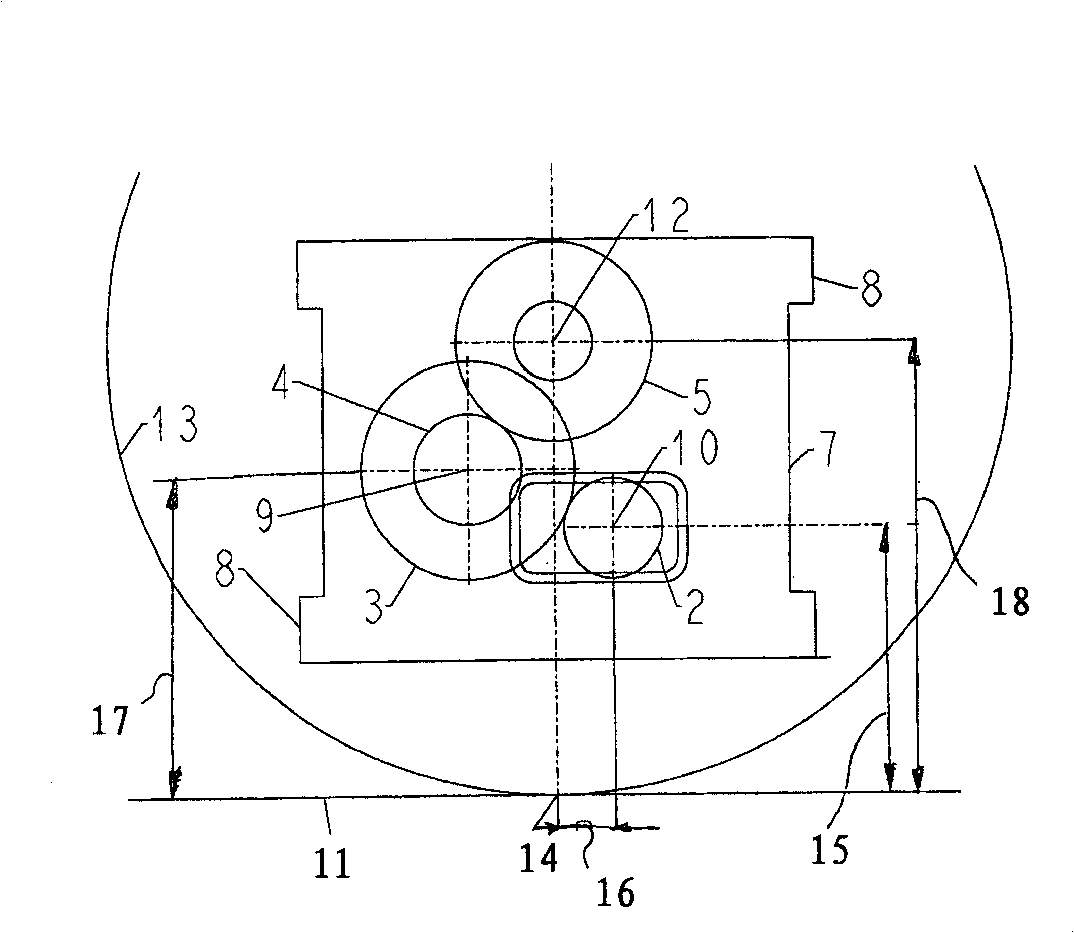
[0013] The basic structure of a portal axle for low-frame vehicles is known from DE 196 04 730 A1, and the invention is to include its features in its entirety except for the wheel-side reduction.

[0014] A differential (not shown) drives an axle 1 , which is connected in a rotationally fixed manner to a drive spur gear 2 . The drive spur gear 2 is operatively connected to a first countershaft spur gear 3 , which is connected in a rotationally fixed manner to a second countershaft spur gear 4 , or is formed in one piece with this countershaft spur gear. The second countershaft spur gear 4 is operatively connected to an output spur gear 5 which drives a not shown vehicle wheel via an output shaft 6 . The wheel gear reducer housing 7 surrounds the wheel gear reducer and has connecting points 8 to which spring bearings (not shown) can be connected, which connect the vehicle axle to the vehicle chassis. The axle 1 is arranged in the upper region of a ...


PUM


Abstract

The invention relates to a portal axle for low-platform vehicles. Said portal axle consists of a drive spur wheel (2) which interacts with a first counter spur wheel (3) which is rotationally fixed to a second counter spur wheel (4) which interacts with a driven spur wheel (5). The vertical distance of the rotational axis (10) of the drive spur wheel to the ground (11) is less than the vertical distance of the counter spur wheels (9, 4) to the ground (11).

Description

technical field [0001] The invention relates to a portal axle, especially for low-frame buses. Background technique [0002] Portal axles of the same type are used in particular in low-floor city buses, for which it is important that the vehicle floor is set so low that passengers can easily board the bus from the sidewalk. It must be taken into account here that the bus has a sufficiently wide center aisle and at the same time does not fall below the lower limit of the ground clearance for driving over obstacles. [0003] DE 196 04 730 A1 discloses a portal axle for low-frame buses, wherein a wheel-side reducer (Portalgetriebe) is driven by a differential via an axle, wherein between the drive pinion and Two spur gears are arranged between the output spur gears, the axes of rotation of these spur gears are arranged at the same height as the axis of rotation of the drive pinion, so as to maintain a power split on the drive pinion, so that the drive pinion is in its diameter...

Claims


Application Information

Patent Timeline
Patent Type & Authority Patents(China)
IPC IPC(8): B60K17/04
CPCB60K17/043B60K17/22
Inventor R·诺伊米勒S·豪斯勒
Owner ZF FRIEDRICHSHAFEN AG
Why Eureka
Try Eureka