Planar light source and liquid crystal display device using the same

A technology for a liquid crystal display device and a light source device, applied in the fields of liquid crystal display devices and surface light source devices, can solve the problems of overheating, shortened life of the linear light source, inappropriate heat distribution of the linear light source, etc. uneven effect

Inactive Publication Date: 2008-11-19
MITSUBISHI ELECTRIC CORP
View PDF6 Cites 2 Cited by
  • Summary
  • Abstract
  • Description
  • Claims
  • Application Information

AI Technical Summary

Problems solved by technology

[0008] However, for the structure of the prior art, it can be clearly seen that the light emitting part of the linear light source, especially the phenomenon of overheating at the electrode part
It can be seen that there is a problem that the heat distribution of the linear light source itself is not suitable, so that the life of the linear light source is significantly shortened.

Method used


Image

  • Planar light source and liquid crystal display device using the same
  • Planar light source and liquid crystal display device using the same
  • Planar light source and liquid crystal display device using the same

Examples


Embodiment 2

[0044] refer to Figure 4 Example 2 of the present invention will be described. Figure 4 It is a front view for explaining the arrangement relationship of each constituent element of the backlight unit 102 of the second embodiment. Figure 4 Only a few elements are shown for simplicity of illustration. Figure 4 The same symbol is used in the Figure 1~3 The same constituent elements in , and repeated descriptions are omitted.

Embodiment 1

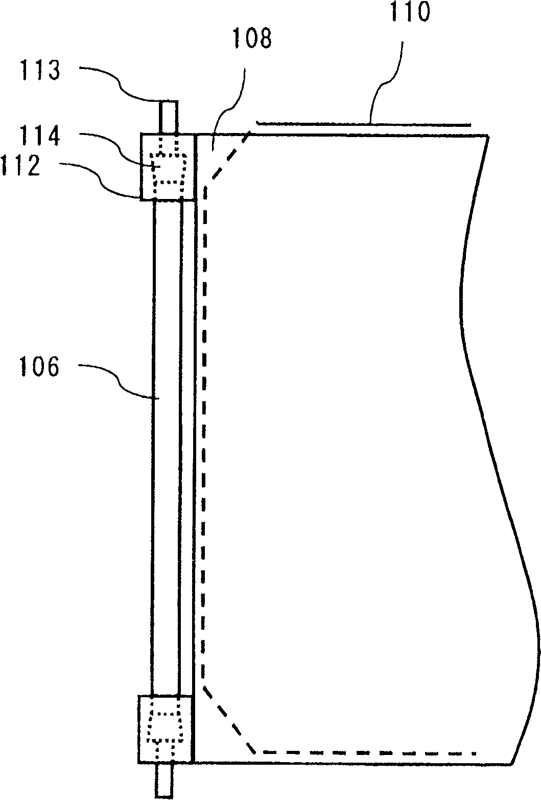
[0045] In Embodiment 1, the end of the vapor chamber 110 spans the entire area facing the linear light source 106 including the electrode portion 114 , and is farther away from the linear light source than the incident side of the light guide plate 108 . In this case, the original purpose of using the vapor chamber 110, that is, the luminous heat of the linear light source 106, or the heat soaking effect of the driving circuit components such as the source driver 104 and the gate driver 105 is reduced, and the occurrence of A case where the degree of unevenness worsens is shown. In addition, due to insufficient heat soaking of the liquid crystal display panel 101 , display unevenness occurs around the panel, and particularly, display unevenness easily occurs near the center of the edge of the panel.

[0046] For this reason, in this embodiment, as Figure 4 As shown, within the range of the position of the linear light source 106, except for the position determining portion 1...

Embodiment 3

[0054] refer to Figure 5 Embodiment 3 of the present invention will be described. Figure 5 It is a front view for explaining the arrangement relationship of each constituent element of the backlight unit 102 of the third embodiment. Figure 5 Only a few elements are shown for simplicity of illustration. Figure 5 The same symbol is used in the Figure 1-3 The same constituent elements in , and repeated descriptions are omitted.

[0055] In this embodiment, the linear light source 106 is a cold cathode tube formed by bending more than once. That is, the linear light source 106 in this embodiment has one or more bent portions. Here, if Figure 5As shown, the linear light source 106 is a U-shaped cold-cathode tube with two bending points obtained by two bending processes. However, the shape of the linear light source 106 is not limited thereto, and an L-shaped light source having one bending point formed by a single bending process may be used. The electrode portion 114 ...


PUM


Abstract

The present invention provides that suppresses the reduction in the life of the light source and the occurrence of uneven display. The backlight unit that one example of the present invention relates to, includes a light guide plate, a linear light source disposed in the light incident side of the light guide plate, a reflective sheet disposed in the rear side of the light guide plate, and a heat spreader sheet disposed in the rear side of the reflective sheet. In this backlight unit, an edge of the heat spreader sheet is placed more inner than the light incident side surface of the light guide plate in the vicinity of an electrode portion of the linear light source. Furthermore another edge of the heat spreader sheet is substantially aligned with an corresponding side surface other than the incident side surface of the light guide plate.

Description

technical field [0001] The present invention relates to a planar light source device and a liquid crystal display device using the planar light source device. Background technique [0002] Generally, in a liquid crystal display device, a backlight unit (backlight unit) is arranged on the back of a liquid crystal display panel (Liquid crystal display panel). For this reason, heat from linear light sources such as cold cathode tubes constituting the backlight unit is transferred to the liquid crystal display panel, making the in-plane heat distribution of the liquid crystal display panel uneven, and problems such as uneven display are likely to occur. [0003] In order to solve the above-mentioned problems, a heat soaking plate with high thermal conductivity such as aluminum is arranged on the back, side, etc. of the light guide plate or the linear light source constituting the backlight unit, thereby making the heat distribution in the liquid crystal display panel uniform (fo...

Claims


Application Information

Patent Timeline
Patent Type & Authority Patents(China)
IPC IPC(8): G02F1/1335
CPCG02F2001/133628G02B6/0071G02F1/133605G02F1/133615G02F1/133628G02F1/1335
Inventor 小川雄二
Owner MITSUBISHI ELECTRIC CORP
Why Eureka
Try Eureka