Light source driving circuit, light source component provided with the light source driving circuit, and display apparatus

A light source driving circuit, light source technology, applied in circuit layout, electric lamp circuit layout, components of lighting devices, etc., can solve problems such as deterioration of sealing resin, shortened life, beam recession, etc.

Inactive Publication Date: 2009-09-02
KYOCERA CORP
View PDF1 Cites 2 Cited by
  • Summary
  • Abstract
  • Description
  • Claims
  • Application Information

AI Technical Summary

Problems solved by technology

If the condensation of mercury occurs, the luminous efficiency of the discharge tube that fluctuates with the mercury vapor pressure will decrease significantly due to the decrease in the vapor pressure of mercury.
In addition, in this way, if the driving is continued in a state where the luminous efficiency is significantly lowered, an excessive load is applied to the discharge tube itself, so the life may be shortened.
In addition, when a light emitting diode (LED) is used as the light source 91, if the LED is driven under a high ambient temperature (for example, 40° C. or higher), the LED chip or the sealing resin that seals the LED chip may deteriorate.
In this way, if the LED chip or sealing resin deteriorates, the transmittance of light will decrease, resulting in beam attenuation.
In addition, if the current flowing through the LED increases, the output (brightness) will increase, but the ambient temperature will increase due to the heat generated by the LED itself, causing the same problem as above.
Therefore, if the light source device 90 of the conventional structure is used in a situation where the ambient temperature changes greatly, such as indoor lighting fixtures, outdoor street lamps, and backlights of liquid crystal display devices, it is difficult to maintain predetermined light source characteristics at a sufficiently high level. state

Method used


Image

  • Light source driving circuit, light source component provided with the light source driving circuit, and display apparatus
  • Light source driving circuit, light source component provided with the light source driving circuit, and display apparatus
  • Light source driving circuit, light source component provided with the light source driving circuit, and display apparatus

Examples


Embodiment Construction

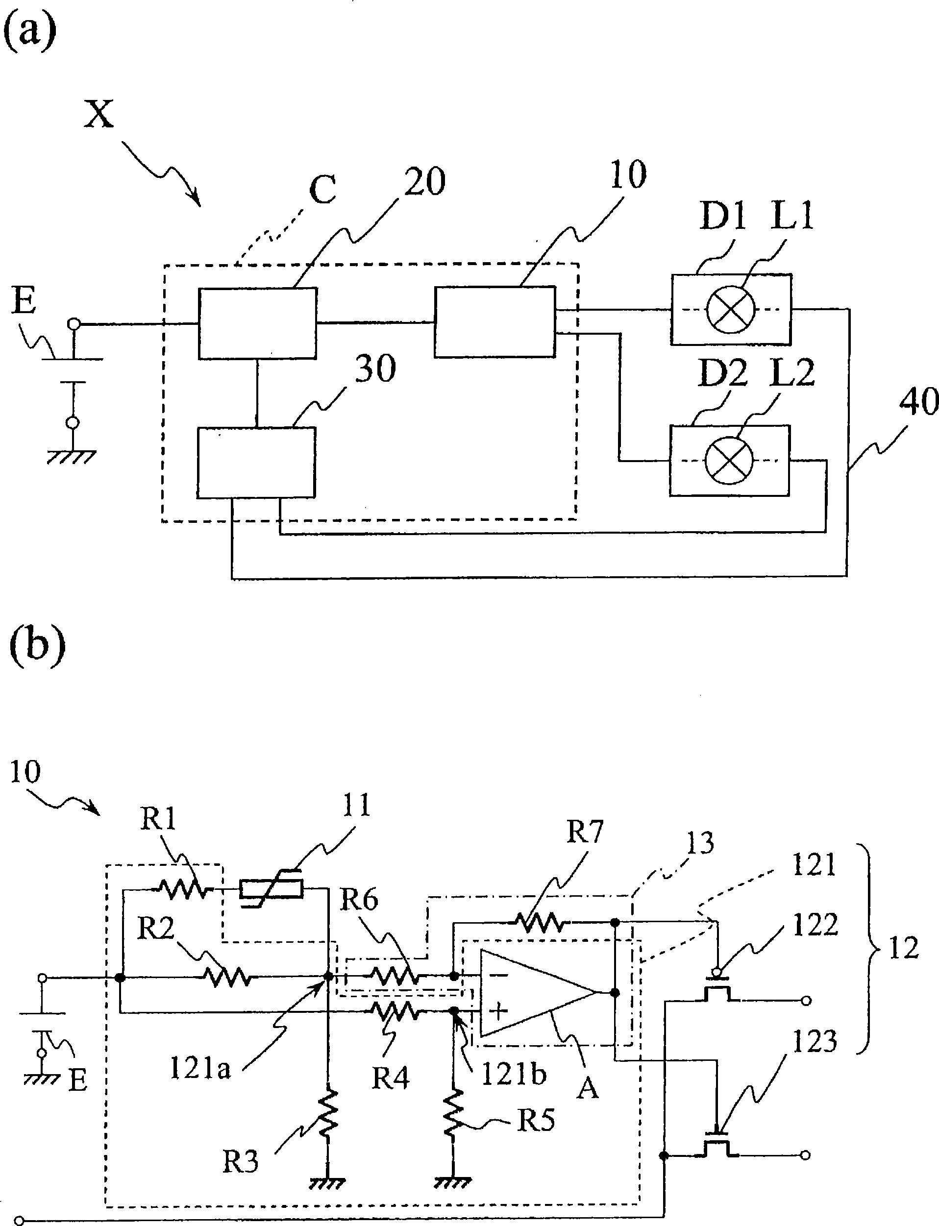
[0030] figure 1 It is a schematic diagram showing the circuit structure of the light source driving circuit X of the present invention, (a) is its overall view, and (b) is an enlarged view of its main part.

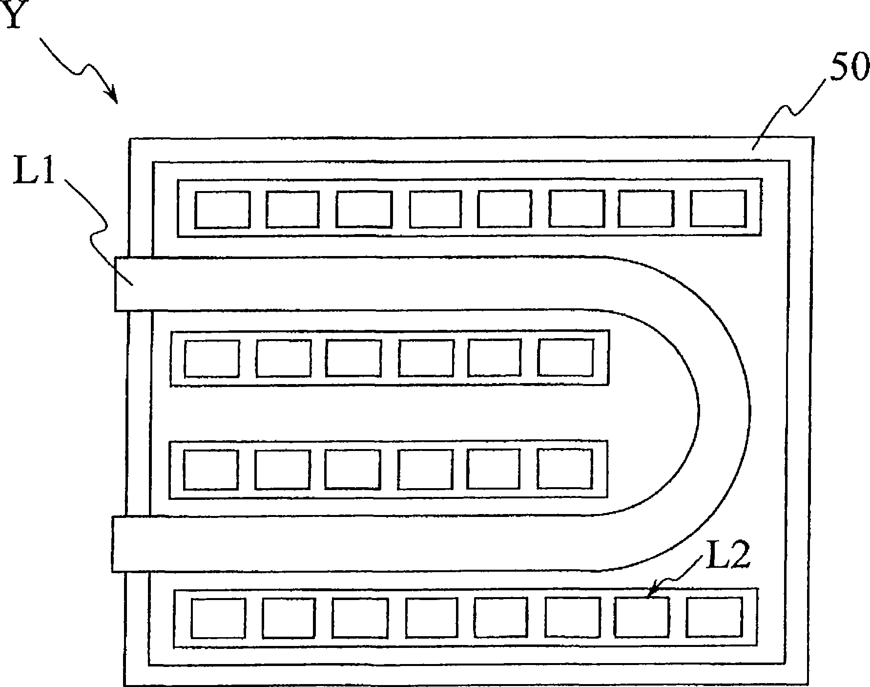
[0031] The light source driving circuit X includes, for example, a controller C formed on a substrate not shown, and drives the first light source L1 or the second light source L2 to emit a desired amount of light. The first light source L1 is at least one light source having sufficiently high light source characteristics when the ambient temperature exceeds the reference temperature, and the second light source L2 is a light source having sufficiently high light source characteristics when the ambient temperature is below the reference temperature. Examples of the first light source L1 and the second light source L2 include cold-cathode discharge tubes, hot-cathode discharge tubes, light-emitting diodes, halogen lamps, xenon lamps, inorganic electroluminescence, organic...


PUM


Abstract

Provided are a light-source drive circuit substrate and a light source component which can drive a light source with sufficiently high light source characteristics even when environmental temperature Provided are a light-source drive circuit substrate and a light source component which can drive a light source with sufficiently high light source characteristics even when environmental temperaturegreatly changes, and a display apparatus which includes the light source component. A light-source drive circuit (X) according to the present embodiment includes a controller (C) configured to drive agreatly changes, and a display apparatus which includes the light source component. A light-source drive circuit (X) according to the present embodiment includes a controller (C) configured to drive a first light source (L1) and a second light source (L2) having at least one light source characteristics higher than those of the first light source (L1) when the environmental temperature is equal tofirst light source (L1) and a second light source (L2) having at least one light source characteristics higher than those of the first light source (L1) when the environmental temperature is equal toor below a reference temperature. The controller (C) includes a selector (10) which selects a first driver (D1) for driving the first light source (L1) when the environmental temperature goes above t or below a reference temperature. The controller (C) includes a selector (10) which selects a first driver (D1) for driving the first light source (L1) when the environmental temperature goes above the reference temperature, and selects a second driver (D2) for driving the second light source (L2) when the environmental temperature becomes equal to or below the reference temperature.he reference temperature, and selects a second driver (D2) for driving the second light source (L2) when the environmental temperature becomes equal to or below the reference temperature.

Description

technical field [0001] The present invention relates to a light source driving circuit for driving a light source such as a discharge tube or a light emitting diode, a light source component provided with the light source driving circuit, and a display device. Background technique [0002] Currently, light source devices that emit light toward an object are being developed in a wide range of fields. Figure 5 It is a diagram showing an example of the circuit configuration of a basic light source device. The light source device 90 includes a light source 91 such as a discharge tube or a light emitting diode, and a driver 92 for driving the light source 91 . A light source device 90 having such a configuration is disclosed in Patent Document 1, for example. [0003] Patent Document 1: JP-A-2-41667 [0004] However, in the light source device 90 having a conventional structure, when a discharge tube or a light emitting diode is used as the light source 91, for example, there ...

Claims


Application Information

Patent Timeline
IPC IPC(8): H05B37/02F21S2/00F21V23/00H01L33/00H05B41/24F21Y101/02G02F1/13357
CPCH05B33/0854G02F1/133604H05B35/00G02F1/133603H05B41/36G02F2001/133612H05B33/0803H05B41/39H05B45/18G02F1/133612H05B45/3725H05B45/10H05B45/395
Inventor 下吉健宇佐美守
Owner KYOCERA CORP
Why Eureka
Try Eureka