Stator of claw-pole shaped motor

A motor and salient-pole technology, which is applied in electric components, synchronous motors with stationary armatures and rotating magnets, electromechanical devices, etc., can solve the problems of thicker thickness, thicker stator, and inability to effectively use the magnetic circuit , to achieve the effect of increasing the output torque

Inactive Publication Date: 2008-12-17
HONDA MOTOR CO LTD
View PDF7 Cites 2 Cited by
  • Summary
  • Abstract
  • Description
  • Claims
  • Application Information

AI Technical Summary

Problems solved by technology

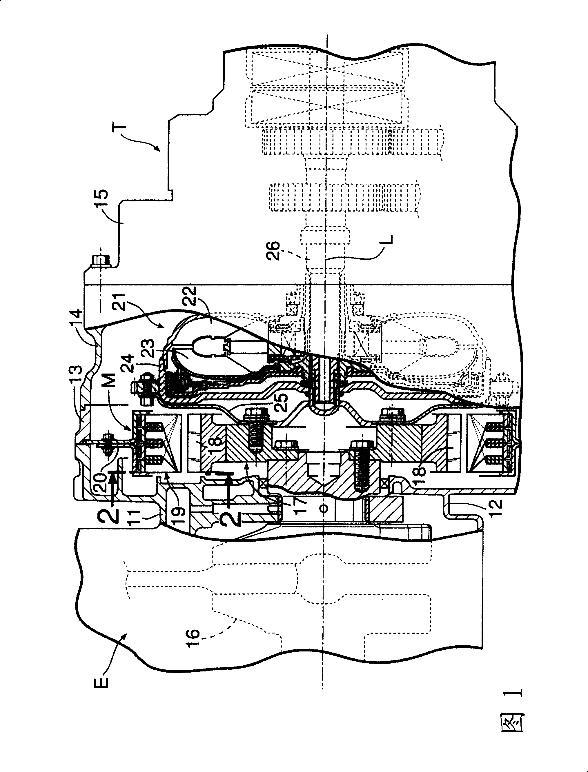
[0004] However, in the prior art described above, three unit stators of U-phase, V-phase, and W-phase are laminated in the axial direction to form a stator. The stator has two teeth and two types of protrusions, so the thickness in the axial direction becomes thicker, and there is a problem that the size of the stator in the axial direction is enlarged when three such unit stators are stacked.
In addition, since the magnetic circuits of the unit stators of each phase are independent, there is a problem that these magnetic circuits cannot be effectively used
[0005] In particular, when such an electric motor is arranged between the engine and the transmission of a hybrid vehicle, it is desired to make it as thin as possible, but it is difficult to meet this requirement because the stator of the above-mentioned prior art is thick.

Method used


Image

  • Stator of claw-pole shaped motor
  • Stator of claw-pole shaped motor
  • Stator of claw-pole shaped motor

Examples


Embodiment 1

[0082] FIG. 27A shows a magnetic circuit of a conventional general m-phase wave winding motor. m is a natural number greater than or equal to 2, and the windings of each phase pass through m staggered slots in a wave shape in such a way that the excitation direction is opposite. At this time, the interlinkage flux of the k-th (1≤k≤m) phase winding is represented by φk-φk+m.

[0083] Fig. 9 (A), (B) shows the magnetic circuit of the m-phase wave winding salient pole type motor with 2m teeth and 2m-1 slots, which is developed in the axial direction of the above-mentioned general m-phase wave winding motor. It can also be seen that the interlinkage magnetic flux of each phase does not change. That is, the interlinkage magnetic flux of the k-th (1≤k≤m-1) phase winding is φk-φ2m-(φk+m-φ2m)=φk-φk+m, which is consistent with the case of FIG. 27A . In contrast to the case where windings other than the m-th phase exist in two slots, the windings of the m-th phase exist in only one sl...

Embodiment 2

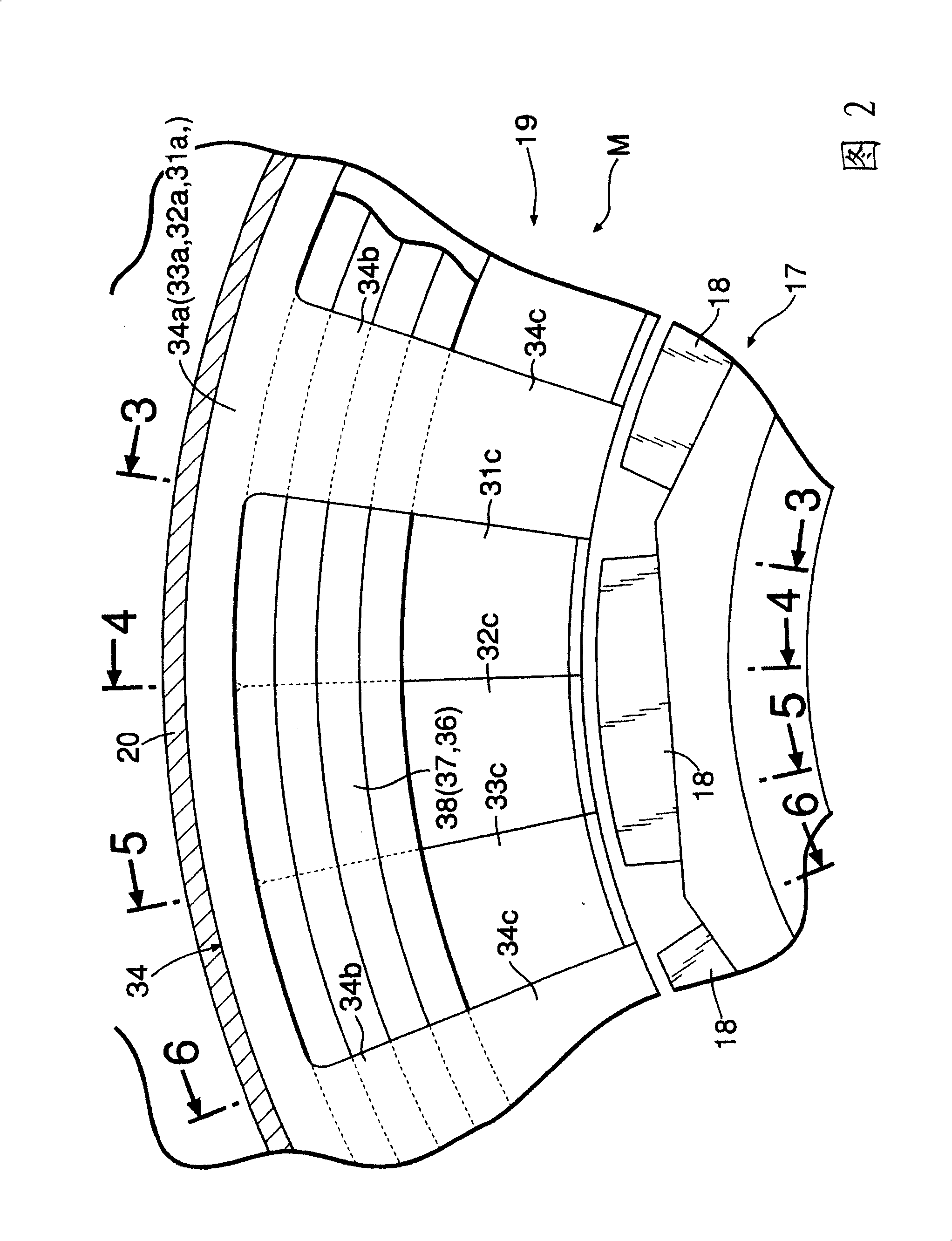
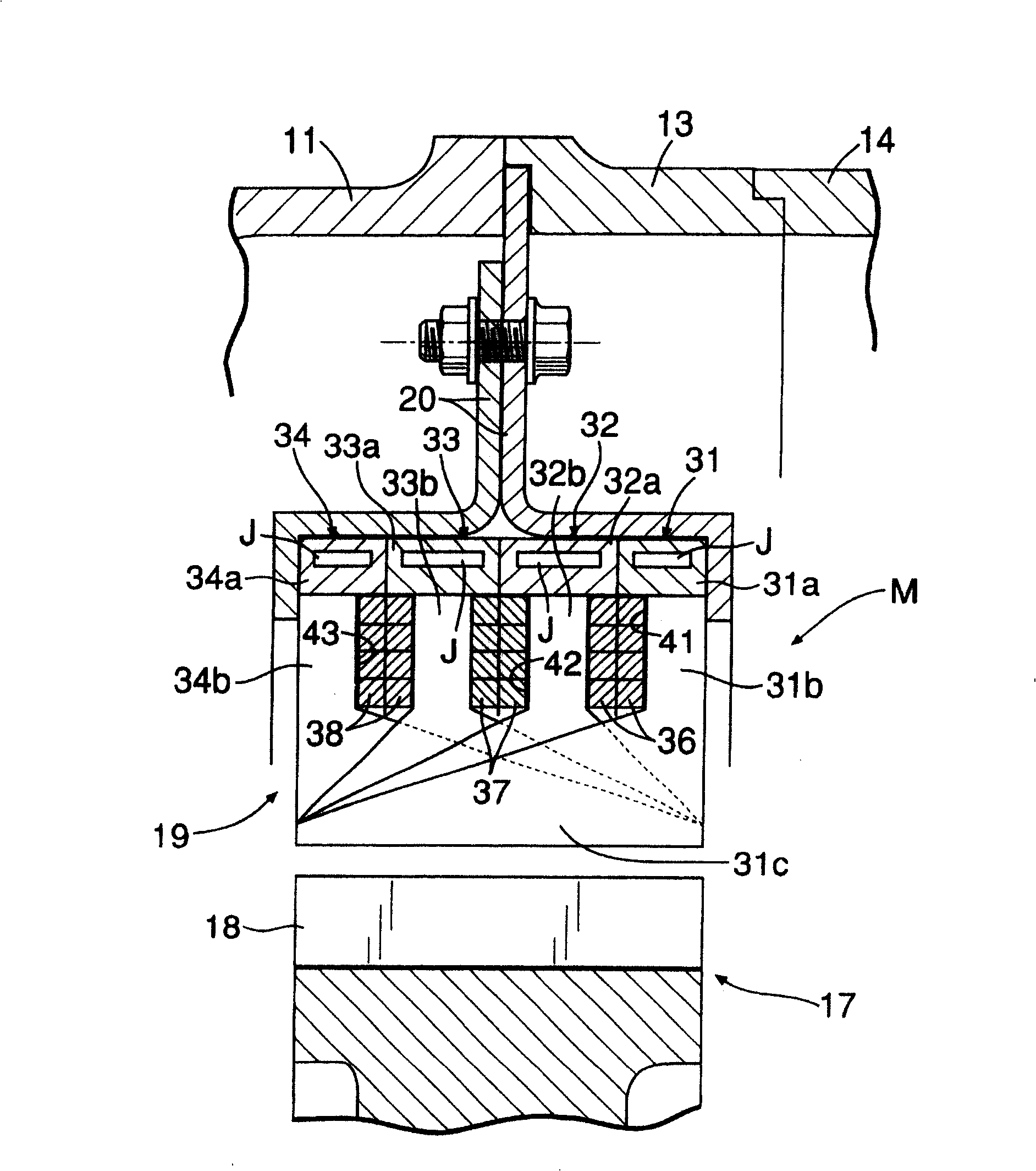
[0105] In the first embodiment, A of the stator 19 + Phase, B + Phase, A - Phase and B - The phase teeth 31b..., 32b..., 33b..., 34b... are arranged so as to be out of phase in the circumferential direction, and the protrusions 31c... , 32c . . . , 33c . . . , 34c . . . have a width equal to the thickness of the stator 19 in the axis L direction. In addition, the width of the permanent magnets 18 of the rotor 17 is equal to the width of the projections 31c..., 32c..., 33c..., 34c..., and the permanent magnets 18 are shared by the projections 31c..., 32c..., 33c..., 34c... of the respective phases. .

[0106] In contrast, in the second embodiment, A of the stator 19 + Phase, B + Phase, A - Phase and B - Phase teeth 31b . . . , 32b . , 33c..., 34c... are also arranged so that the phases are the same. On the other hand, the permanent magnets 18 arranged on the outer periphery of the rotor 17 ... the protrusions 31c ..., 32c ..., 33c ..., 34c ... corresponding to the res...

Embodiment 3

[0110] The third embodiment is a modification of the above-mentioned second embodiment. In the second embodiment, the phases of the protrusions 31c..., 32c..., 33c..., 34c... of each phase are aligned, and the phases of the permanent magnets 18... They are shifted by 360° / 2m=90° respectively. In contrast, in the third embodiment, the phases of the protrusions 31c..., 32c..., 33c..., 34c... of each phase are shifted by 360° / 2m=90°, so that each The phases of the permanent magnets 18 . . . of the phase coincide. Also according to this third embodiment, the same effect as that of the second embodiment can be achieved. And if the permanent magnets 18... are not divided into four stages, and the same permanent magnets 18... as the stator 19 of the first embodiment are used, the number of parts can be reduced.

[0111] In addition, when the magnetic circuit of the conventional m-phase wave winding motor shown in FIG. 27A is divided in the circumferential direction as shown in FIG. ...


PUM


Abstract

Alternately arrange 2m stator rings in the axial direction, where m is a natural number greater than or equal to 2 (m=2 in the embodiment), each stator ring is formed with a plurality of teeth (31b-34b) and connects the teeth to each other 2m-1 slots (41, 42, 43) are formed between 2m stator rings, and the windings (36, 37, 38) in each slot (41, 42, 43) will be accommodated in the return path The windings (36, 37, 38) in the slots (41, 42, 43) at a distance of m are connected in series so that the excitation directions are opposite, so that the phases of the magnetic flux passing through the teeth (31b-34b) of each stator ring are respectively staggered by 360 ° / 2m, it is possible to abolish the winding portion (transition portion) that does not contribute to the torque, and since the magnetic circuit of each phase is shared through the return path (31a to 34a), a thin and high-output salient pole motor can be obtained, and Since the magnetic circuit of the wave winding motor is formed, the output torque can be increased compared with the salient pole concentrated winding motor.

Description

technical field [0001] The present invention relates to a stator of a salient pole motor, which accommodates a plurality of windings wound in a plane perpendicular to the axis in a plurality of slots formed between a plurality of teeth, the plurality of teeth being aligned in the axial direction. on side-by-side configuration. Background technique [0002] According to the following Patent Document 1, a stator of such a salient pole motor is disclosed. It has three unit stators corresponding to each of the U-phase, V-phase, and W-phase, each unit stator having two teeth spaced apart in the axial direction and a return path connecting these teeth at radially outer ends, And it is formed so that a cross section may be U-shaped. In addition, an independent magnetic circuit is formed by energizing an annular winding housed inside a unit stator having a U-shaped cross section, so that the polarity protruding from the radially inner ends of the two teeth facing the rotor Differ...

Claims


Application Information

Patent Timeline
Patent Type & Authority Patents(China)
IPC IPC(8): H02K1/14H02K3/18H02K3/28H02K9/19H02K9/22H02K16/04H02K21/16
CPCH02K1/145H02K16/04H02K2201/06
Inventor 今井信幸青木新菊地博幸关正広高桥忠伸田嶋茂
Owner HONDA MOTOR CO LTD
Why Eureka
Try Eureka