
Tower bubbling stuffing with vortex-flow and defrosting function

A functional and column technology, applied in the field of petrochemical column packing and mist eliminators, which can solve problems such as coupling of unseen mass transfer processes

Inactive Publication Date: 2008-12-24
褚雅志
View PDF2 Cites 1 Cited by
  • Summary
  • Abstract
  • Description
  • Claims
  • Application Information

AI Technical Summary

Problems solved by technology

In the existing technology, there have been many packings and trays with different structures, and they all belong to the above-mentioned design ideas. Although they have also achieved good improvement effects, there has been no coupling of the mass transfer process between the packing and the trays so far. design ideas together

Method used


Image

  • Tower bubbling stuffing with vortex-flow and defrosting function
  • Tower bubbling stuffing with vortex-flow and defrosting function
  • Tower bubbling stuffing with vortex-flow and defrosting function

Examples


Embodiment 1

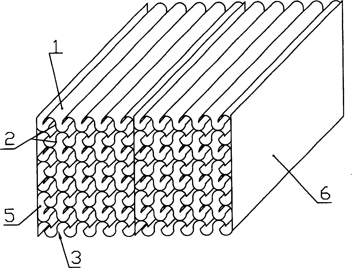
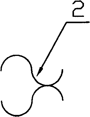
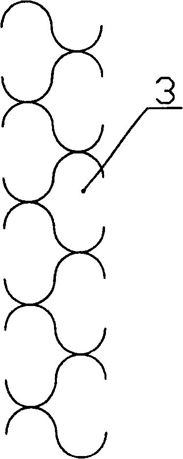
[0025] See figure 1 , It includes an S-shaped wave plate 1, the S-shaped wave plate is butted in opposite directions to form a packing unit 2, such as figure 2 As shown, a plurality of the packing units 2 are arranged longitudinally to form a packing unit row 3, such as image 3 Shown; see Figure 4 , A plurality of the packing unit rows are arranged horizontally and parallel to form a packing block 4, and the packing unit rows and the rows are partially overlapped, so that the butt closed end of the front packing unit extends into the C-shaped open end of the rear packing unit. There are half packing unit row sealing plates 5 and 6 on both sides of multiple packing unit rows, thus forming such figure 1 A completed structured packing shown.

[0026] Refer to Figure 5, when the sprayed liquid enters the packing, a part of the liquid will be temporarily stored in the semicircular groove 1-1 of each S-shaped wave plate, and the semicircle on the semicircular groove 1-1 is reversed...

Embodiment 2

[0028] The structure equivalent to the structure of the above example is: see Figures 6 and 7, it includes a perpendicularly bent right-angled S-shaped plate, the right-angled S-shaped plate is butted in opposite directions to form a packing unit (8-1), multiple The packing units (8-1) are arranged longitudinally to form a packing unit row (8), and a plurality of the packing unit rows 8 are arranged in parallel to form a packing block (7), and there is a partial overlap between the packing unit rows and the rows. The butt closed end of the front packing unit extends into the C-shaped open end of the rear packing unit, and half packing unit sealing plates 9 and 10 are arranged on both sides of the packing block 7 to form a complete structured packing.

[0029] The installation structure of the packing (including the packing described in Example 1 and Example 2) in the tower is shown in Figure 8 and Figure 10. When the tower diameter is small, the packing 11 can be directly placed o...


PUM


Abstract

The invention is a tower vessel bubbling filler having both the swirling and defogging functions, which includes S-shaped waved plates, the S-shaped waved plates are butt-jointed reversely by twos to form a packing unit, a plurality of packing units form a packing unit row by longitudinal arrangement, then a plurality of packing unit rows form a packing block by lateral and parallel arrangement, and the packing unit rows are laid to partially overlap each other, the butt-joint close end of the front row of packing unit is extended into the C-shaped open end of the rear row of packing unit, half of the close board of the packing unit row is arranged on the two sides of the packing block, thus forming an integrated regular packing process. The invention also has the bubbling and mass transfer process while fulfilling the process of packing gas and liquid countercurrent contacting and mass transfer, and the structure of the bubbling is arranged compactly, therefore, the mass transfer efficiency of the filler is extremely improved.

Description

Technical field [0001] The invention relates to a petrochemical tower packing and a mist eliminator, specifically, it is a tower bubbling packing with a cyclone defogging function. Background technique [0002] Distillation towers are mainly divided into two types, one is a plate tower and the other is a packed tower. The main structure of the packed tower is to install a liquid phase distributor and multi-layer packing in the tower. The packing is an important part of the gas and liquid two-phase mass transfer. The mass transfer process of the packing is: the liquid phase drops into the packing through the distributor spray , The liquid phase forms a downward-flowing liquid film on the structural surface of each packing unit. The liquid film contacts the rising gas phase countercurrently for mass transfer, so that the lighter substances in the liquid phase are heated and evaporated by the gas phase and rise together with the gas phase. The heavier components in the gas phase are...

Claims


Application Information

Patent Timeline
Patent Type & Authority Patents(China)
IPC IPC(8): B01J19/32B01D3/14
Inventor 褚雅安
Owner 褚雅志
Learn More