

Machine and method for machining rails
A track and mechanical technology, applied in the direction of track, track laying, track maintenance, etc.
- Summary
- Abstract
- Description
- Claims
- Application Information
AI Technical Summary
Problems solved by technology
Method used
Image

Examples
Embodiment Construction
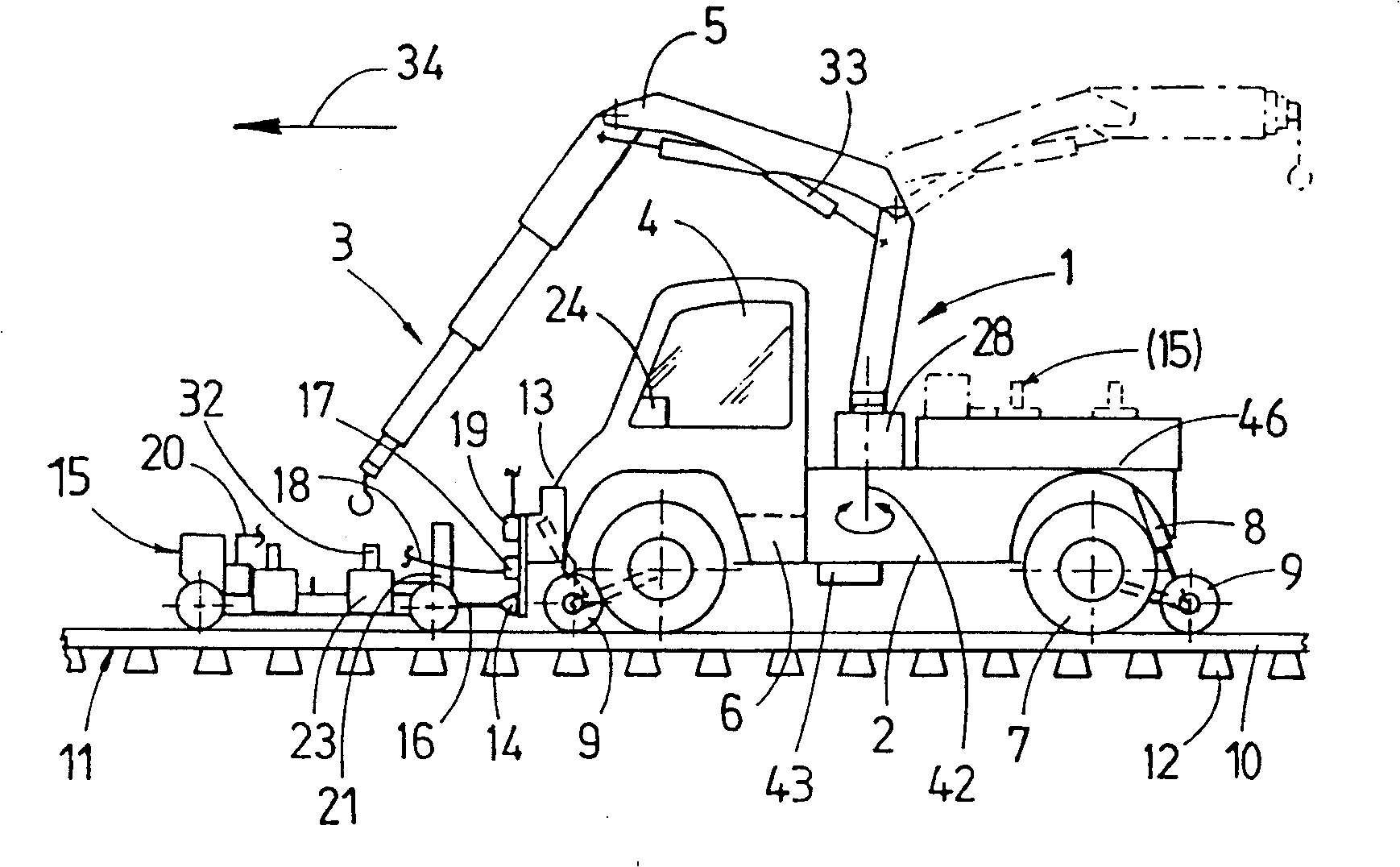
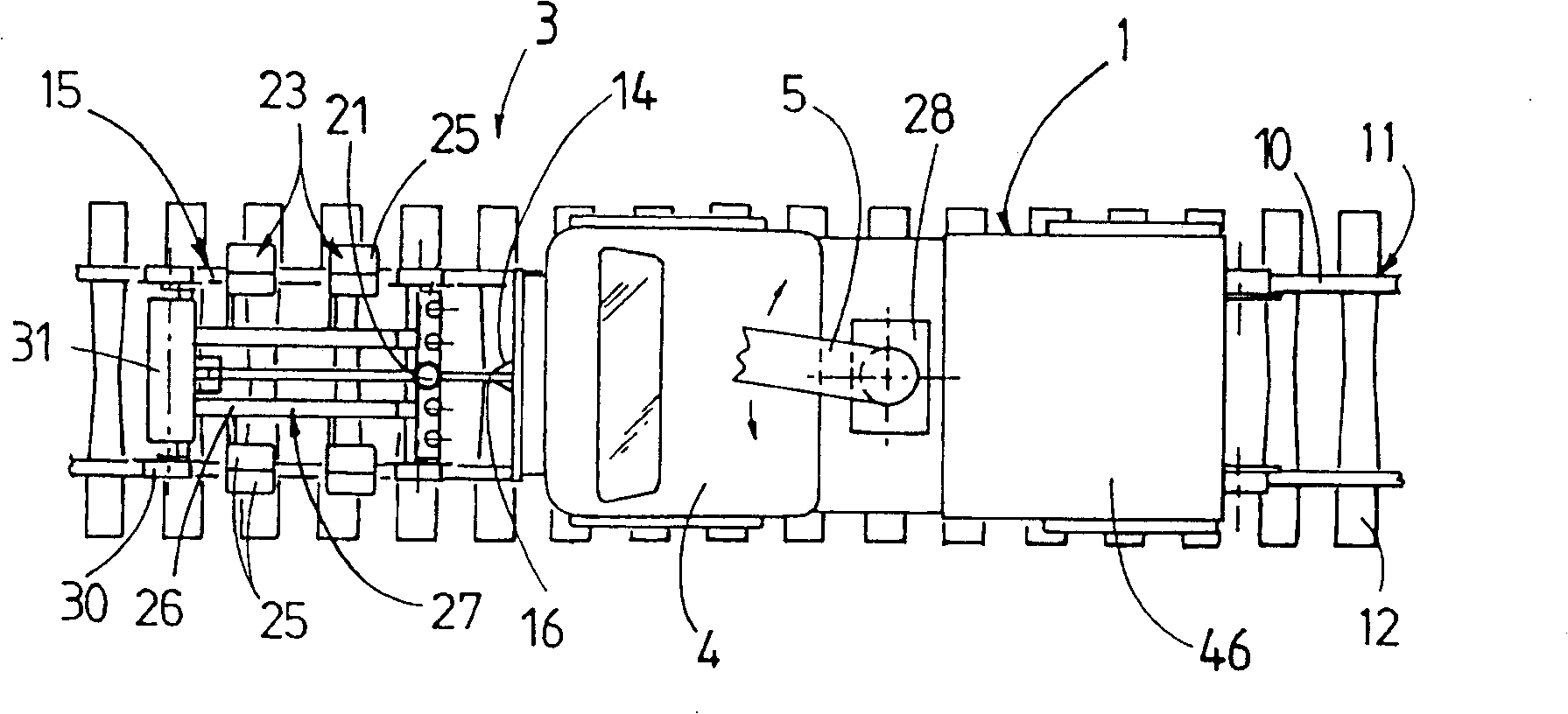
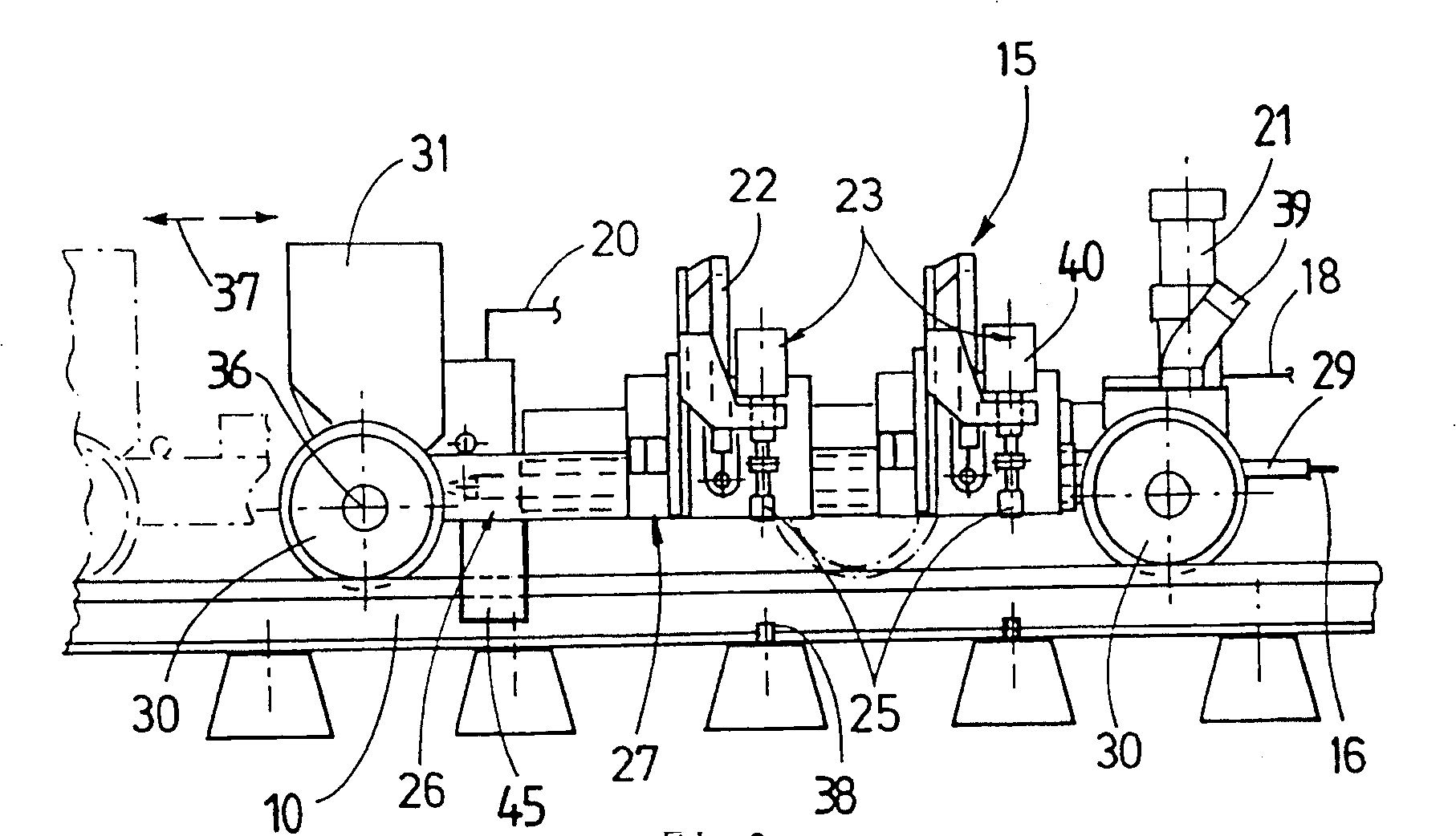
[0022] figure 1 with 2 The shown machine 3 consists of a transport vehicle 1 and a work vehicle 15 . The transport vehicle 1 has an undercarriage 2 with a loading area 46 , a driver's cab 4 , a crane arm 5 and a travel drive 6 . In order to adapt to different running modes, the transport vehicle has a road running mechanism 7 and a height-adjustable rim wheel 9 utilizing a driving device 8 . The rimmed wheel 9 can be placed on a rail 10 of a track 11 with sleepers 12 . The jib 5 with the drive 33 is used to lower the work vehicle 15 from the loading area 46 onto the rail 11 or vice versa. The crane arm can be rotated by means of the rotary drive 28 about a rotary axis 42 perpendicular to the loading area 46 . The work vehicle 15 is equipped with a suspension device 32 for this reason.
[0023] A coupling device 14 is fixed to the vehicle front end 13 of the underframe 2 along the working direction 34 for connecting or disconnecting with a coupling device 16 of the work ve...
PUM
 Abstract
Description
Claims
Application Information