Dispersion detecting device of amount of suction air

A technology for detection of intake air volume and deviation, applied in electrical control, machine/engine, output power, etc., to solve problems such as deterioration of exhaust emissions, torque fluctuations of internal combustion engines, deviation of intake air volume, etc.

Inactive Publication Date: 2008-12-24
TOYOTA JIDOSHA KK
View PDF9 Cites 0 Cited by
  • Summary
  • Abstract
  • Description
  • Claims
  • Application Information

AI Technical Summary

Problems solved by technology

[0003] However, in an internal combustion engine with a variable valve drive, the amount of intake air is determined by the operating angle and lift, so when there is a difference in the operating angle and lift between cylinders, this will cause a difference in the amount of intake air between cylinders. reason
The influence of the deviation of the action angle and lift on the deviation of the intake air volume is particularly significant at small action angles and small lifts with a small intake air volume. When the deviation of the intake air volume becomes too large , will cause the torque fluctuation of the internal combustion engine, which will cause the deterioration of exhaust emissions

Method used


Image

  • Dispersion detecting device of amount of suction air
  • Dispersion detecting device of amount of suction air
  • Dispersion detecting device of amount of suction air

Examples


Embodiment approach 1

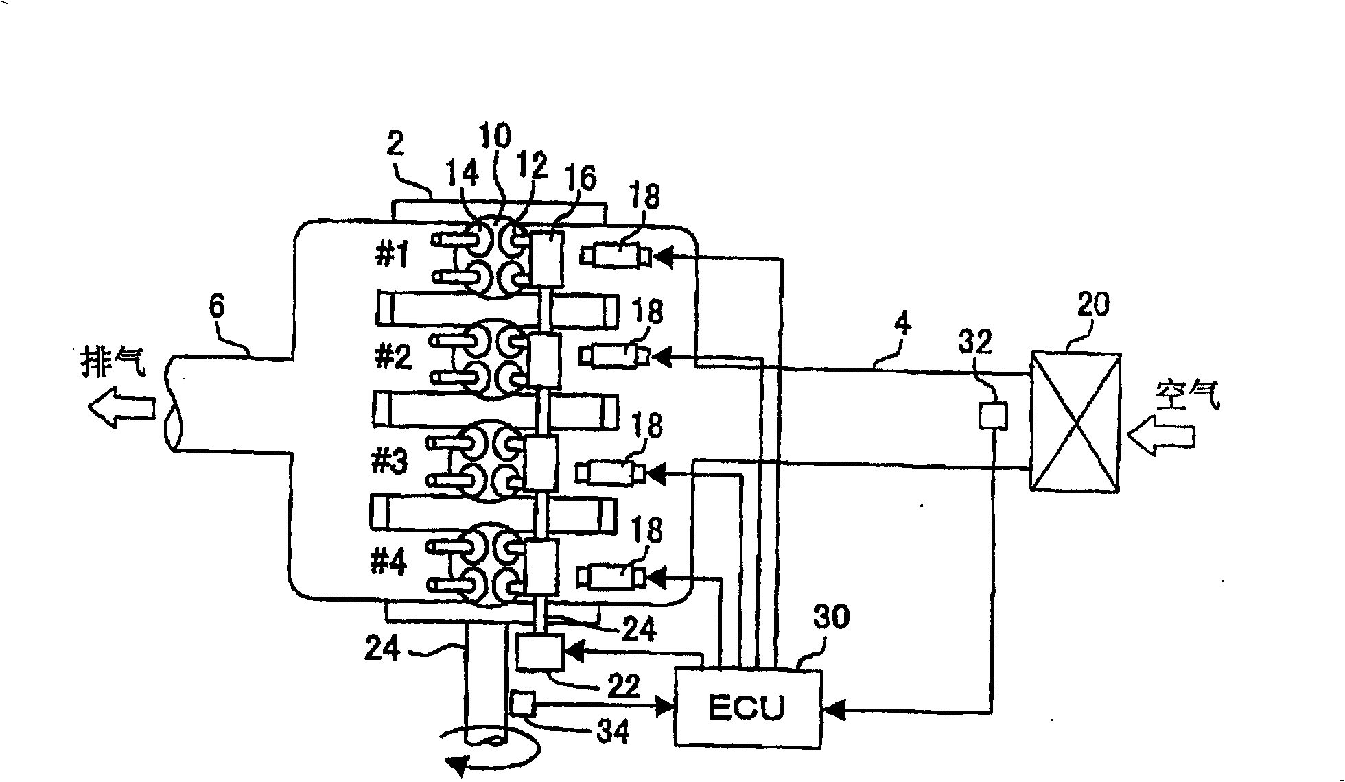
[0072] Below, refer to Figure 1 to Figure 6 Embodiment 1 of the present invention will be described.

[0073] figure 1 It is used to describe the structure of an internal combustion engine to which an intake air amount deviation detecting device according to an embodiment of the present invention is applied. The internal combustion engine 2 of the present embodiment is configured as an inline four-cylinder internal combustion engine having four cylinders #1 to #4.

[0074] The internal combustion engine 2 has an intake passage 4 through which air is introduced and an exhaust passage 6 through which combustion gas is discharged. An air cleaner 20 is provided at the upstream end of the intake passage 4 , and an air flow meter 32 for measuring the amount of intake air (inflow of air per unit time) is provided at a downstream portion close to the air cleaner 20 . The downstream side end portion of the intake passage 4 and the upstream side end portion of the exhaust passage 6 ...

Embodiment approach 2

[0096] Below, refer to Figure 7 Embodiment 2 of the present invention will be described.

[0097] As the intake air amount deviation detecting device according to the second embodiment of the present invention, in the first embodiment, the ECU 30 can execute Figure 7 program instead of Figure 5 program to achieve.

[0098] In Embodiment 1, although the variation in the amount of intake air generated among the cylinders is detected, it is not detected which cylinder has a large amount of intake air and which cylinder has a small amount of intake air. In order to individually adjust the operating angle and lift of the intake valve 12 of each cylinder, it is desirable to be able to grasp the amount of deviation of the intake air amount from the reference value for each cylinder. The deviation of the intake air amount for each cylinder can be detected by controlling the fuel injection amount for each cylinder according to the basic method described above. That is, when the ...

Embodiment approach 3

[0110] Below, refer to Figure 8 Embodiment 3 of the present invention will be described.

[0111] As the intake air amount deviation detecting device according to the third embodiment of the present invention, in the first embodiment, the ECU 30 can execute Figure 8 program instead of Figure 5 program to achieve.

[0112] In Embodiment 2, by changing only the fuel injection amount of a specific cylinder among a plurality of cylinders, a deviation in the intake air amount of the cylinder is detected. However, combustion occurs sequentially in each cylinder, and the torque and rotation speed fluctuate under the influence of the combustion state of the cylinder currently in the combustion process. Therefore, even when the fuel injection amounts of all cylinders are changed uniformly as in the first embodiment, by monitoring the change in torque or rotational speed in the combustion stroke of each cylinder for each cylinder and measuring the vibration amplitude, it is possib...


PUM


Abstract

An intake air quantity variation detecting device capable of accurately detecting a variation in intake air quantity between cylinders in an internal combustion engine having the plurality of cylinders. A fuel injection quantity is changed from an injection quantity in a stoichiometric operation to an injection quantity increasing side or an injection quantity decreasing side. The width of a variation in torque or rotational speed at that time is obtained, and the width of the variation in the torque or the rotational speed is outputted as an index value indicating the degree of the variation in the intake air quantity between the cylinders.

Description

technical field [0001] The present invention relates to a detecting device for detecting deviations in the amount of intake air between cylinders in an internal combustion engine having a plurality of cylinders. Specifically, the present invention relates to a variable valve drive used in a variable valve drive having a variable operating angle or lift of an intake valve. Appropriate detection devices in the internal combustion engine of the device. Background technique [0002] Conventionally, an internal combustion engine having a variable valve gear capable of variably controlling the operating angle or lift of an intake valve is known. In such an internal combustion engine, since the operating angle and lift of the intake valve are variably controlled, the amount of intake air can be controlled by the operating angle and lift without using a throttle valve. In this case, since no negative pressure is generated in the intake pipe, the pumping loss of the internal combust...

Claims


Application Information

Patent Timeline
Patent Type & Authority Patents(China)
IPC IPC(8): F02D45/00F02D41/04F02D41/18F02D13/02
Inventor 中坂幸博
Owner TOYOTA JIDOSHA KK
Why Eureka
Try Eureka