
Nipper mechanism for a combing machine

A comber and clamp technology, used in combers, textiles and papermaking, fiber processing, etc., can solve problems such as inability to determine whether fibers are taken away, retained or combed out by circular combing machines, etc.

Inactive Publication Date: 2009-01-07
MASCHINENFABRIK RIETER AG
View PDF5 Cites 1 Cited by
  • Summary
  • Abstract
  • Description
  • Claims
  • Application Information

AI Technical Summary

Problems solved by technology

As a result, it is not possible to determine whether these fibers are carried away during the separation process (which is equally important as the drawing process), nor whether they are retained or combed out by the circular card during the subsequent carding process

Method used


Image

  • Nipper mechanism for a combing machine
  • Nipper mechanism for a combing machine
  • Nipper mechanism for a combing machine

Examples


Embodiment Construction

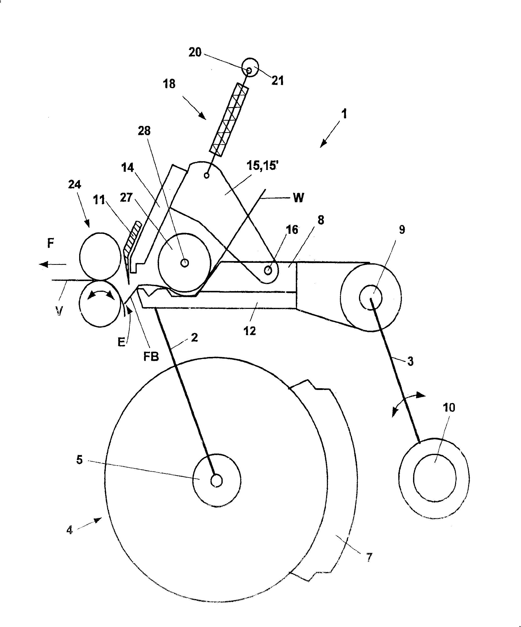
[0023] figure 1 A known clamping device 1 (referred to simply as pliers) is shown, which can be pivotally moved by means of crank arms 2 , 3 after assembly. In this case, two crank arms 2 mounted in each housing near the sides of the circular comb 4 are mounted on the shaft 5 of the circular comb, eg in a pivoting manner. The circular comb 4 has a comber section 7 on part of its circumference. The other end of the pivot arm 2 is fixed on the nipper mount 8 in a rotatable manner. The rear pivot arm 3 (there can also be two) is mounted on the pincer shaft 10 in a torsion-proof manner. The free end of the pivot shaft 3 on the other side is connected in a rotational manner to the nipper mount 8 by means of a shaft 9 .

[0024] Pliers 1 mainly include a lower nipper 12 fixedly connected to the nipper mount 8 and an upper nipper 14 (some are also called nippers) fixed to two pivot arms 15, 15'. These pivot arms are pivotally mounted to the nipper mount 8 by means of pivot shafts...


PUM


Abstract

A textile combing machine has an adjustable guide (32) regulating a gap (E) between a lower tong plate (12) and a clamp line defined by the pair of opening cylinders (24). The gap is regulated at the tong position of maximum advancement. A textile manufacturing combining assembly has a tong station with a tong frame (8) moving back and forth. The tong frame has a lower tong plate (12) whose lip (30) forms a clamping point against the upper clamp plate (14). An assembly within the clamp feeds a fibre mass (W) while the clamp assembly moves back and forth. The fibres (W) feed to a pair of opening cylinders (24) within the machine frame. A round rotating comb is located under the lower clamp plate (12) and removes loose tufts (FB). Guides (32) vary the selected length of tufts removed or passed according to the fibre feed mode, maintaining the combed material within a minimum and constant separation range (E). The adjustable guide (32) regulates the gap (E) between the lower tong plate (12) and clamp line defined by the pair of opening cylinders (24) at the tong position of maximum advancement.

Description

technical field [0001] The invention relates to a clamping device for a combing machine, which has a nipper frame capable of moving back and forth, a lower nipper on the nipper frame, and the lower nipper located within the range of the edge of the nipper can move with the The upper nipper mounted on the nipper frame together forms a jaw or a gripping point; said nipper device also includes a feed mechanism inside it for feeding the fibrous material during the forward and backward movement of the nipper device, Therefore, the detaching roller pair is mounted downstream of the nipper device on the machine frame, the comber is mounted rotatably and arranged below the lower nipper for combing the fiber tufts. Background technique [0002] In fact, it is necessary to adjust the proportion that will be combed out on the comber (abbreviated as comber waste or noil) according to the needs. The proportion of noil is between 5-20%, depending on the desired quality of the yarn, which...

Claims


Application Information

Patent Timeline
IPC IPC(8): D01G19/16
CPCD01G19/16
Inventor D·索默U·斯图茨
Owner MASCHINENFABRIK RIETER AG
Features
  • Generate Ideas
  • Intellectual Property
  • Life Sciences
  • Materials
  • Tech Scout
  • Unparalleled Data Quality
  • Higher Quality Content
  • 60% Fewer Hallucinations
Learn More