Fuel cell system

A fuel cell system and fuel cell technology, applied in the direction of fuel cells, fuel cell additives, circuits, etc., can solve problems such as difficult and large-scale pressure regulation

Active Publication Date: 2009-01-07
TOYOTA JIDOSHA KK
View PDF7 Cites 6 Cited by
  • Summary
  • Abstract
  • Description
  • Claims
  • Application Information

AI Technical Summary

Problems solved by technology

For decompression of high-pressure fuel gas, for example, a pressure regulating valve (regulator valve) can be used, but it is difficult to adjust the pressure in a wide range with a single pressure regulating valve

Method used


Image

  • Fuel cell system
  • Fuel cell system
  • Fuel cell system

Examples


no. 1 example

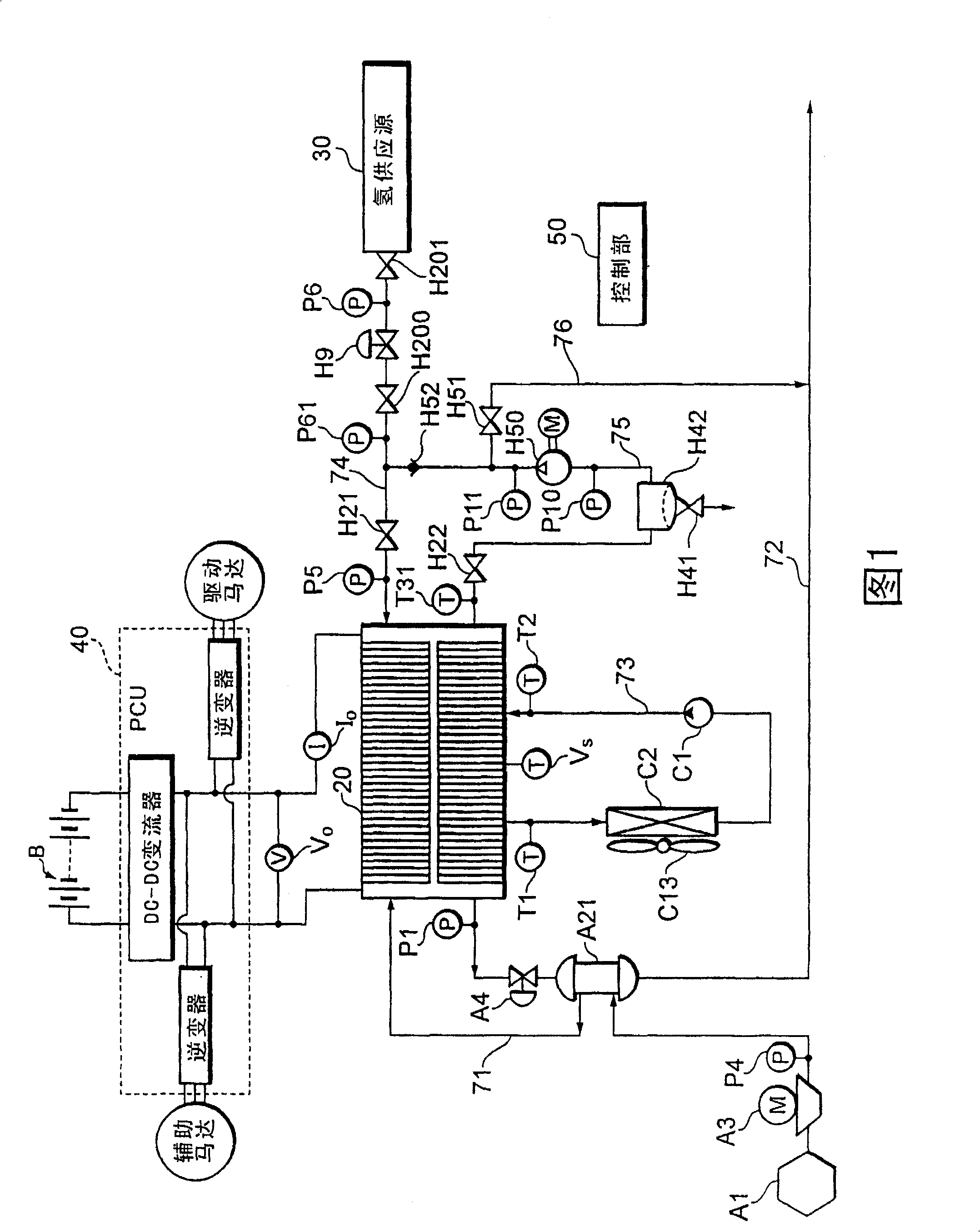
[0045] FIG. 1 shows an example of a fuel cell system to which the first embodiment of the present invention is applied.

[0046] As shown in the figure, air (outside air) as an oxidizing gas is supplied to the air supply port of the fuel cell 20 via the air supply passage 71 . The air supply path 71 is provided with an air filter A1 for removing particulates from the air, a compressor A3 for pressurizing the air, a pressure sensor P4 for detecting the pressure of the supplied air, and a humidifier A21 for adding predetermined moisture to the air. The compressor A3 is driven by an assist motor described later, and constitutes a purification unit together with a control program of the control unit 50 described later. In addition, an air flow meter (flow meter) for detecting the air flow rate is provided in the air filter A1.

[0047] Air off-gas exhausted from the fuel cell 20 is exhausted to the outside through the exhaust passage 72 . The exhaust passage 72 is provided with ...

no. 2 example

[0099]Next, a second embodiment of the present invention will be described with reference to FIG. 11. FIG. In this figure, the parts corresponding to those in FIG. 1 are assigned the same reference numerals, and descriptions of the relevant parts are omitted.

[0100] In this embodiment, the return point of the hydrogen gas from the hydrogen circulation passage 75 is set on the upstream side of the pressure regulating valve H9. The output of the hydrogen pump H50 is regulated by the pressure regulating valve H9. This makes it less likely to be affected by the discharge pressure of the hydrogen pump H50 and its pressure fluctuations. In addition, as in the first embodiment, the pressure of the hydrogen gas supplied to the anode is adjusted by the combination of the pressure regulating valve H9 and the opening degree regulating valve H200. The hydrogen pressure regulation based on various control modes of the opening degree regulating valve H200 as described above can be conti...

no. 3 example

[0102] Fig. 12 shows a third embodiment of the present invention. In this figure, the parts corresponding to those in FIG. 1 are assigned the same reference numerals, and descriptions of the relevant parts are omitted.

[0103] In this embodiment, the pressure regulating valve H9 is replaced with a back pressure valve (back pressure regulating valve) H10. H8 in the figure is a pressure reducing valve. The valve opening degree of the back pressure valve H10 is adjusted so that the downstream side of the back pressure valve H10 becomes a predetermined pressure, and the power generation and discharge of the fuel cell 20 are controlled by adjusting the opening of the opening degree regulating valve H200 provided downstream. Capacity, etc. In addition, the valve opening correction and abnormality judgment of the back pressure valve H10 can be performed on the basis of the opening degree and the secondary pressure of the back pressure valve H10 by the same method as that described...


PUM


Abstract

A fuel cell system that generates electricity using an electrochemical reaction of fuel gas and oxidizing gas, having: a pressure adjustment valve which is provided on a fuel gas supply path for conducting the fuel gas from a fuel gas supply source to a fuel cell and which adjusts the supply gas pressure of the fuel gas; a degree of opening adjustment valve provided downstream of the pressure adjustment valve on the fuel gas supply path, the degree of opening thereof being set in stages or continuously in accordance with a degree of opening signal; and control means that adjusts the degree of opening adjustment signal in accordance with the operating condition of the fuel cell system and controls the state quantity of fuel gas supplied to the fuel cell to a target quantity. In this way, the pressure of fuel gas (for example, hydrogen gas) whose pressure has been reduced by the pressure adjustment valve can be further adjusted to the target pressure by the degree of opening adjustment valve provided downstream of the pressure adjustment valve in accordance with the operating condition of the fuel cell system.

Description

technical field [0001] The present invention relates to a fuel cell system for generating electricity using a fuel gas and an oxidizing gas. Background technique [0002] In a fuel cell system, fuel gas (hydrogen) is compressed and stored in a high-pressure tank. When the fuel cell system is operating, the fuel gas is depressurized to a required pressure and then supplied to the fuel cell. For example, a pressure regulating valve (regulator valve) can be used to depressurize the high-pressure fuel gas, but it is difficult to adjust the pressure over a wide range with a single pressure regulating valve. Therefore, for example, Japanese Patent Laid-Open No. 11-154528 proposes the following fuel cell system, that is, two pressure regulating valves are arranged in series to decompress the pressure of the fuel gas step by step, and the depressurized fuel The gas is supplied via a solenoid valve, so that an inexpensive solenoid valve (on-off valve) for low air pressure can be us...

Claims


Application Information

Patent Timeline
Patent Type & Authority Patents(China)
IPC IPC(8): H01M8/04
CPCH01M8/04664H01M8/04343H01M8/04552H01M8/0488H01M8/0494Y02E60/50H01M8/04097H01M8/04388H01M8/04761H01M8/04432H01M8/04559H01M8/04395H01M8/04402H01M8/0441H01M8/04753H01M8/04358H01M8/04
Inventor 吉田尚弘
Owner TOYOTA JIDOSHA KK
Why Eureka
Try Eureka