Digital type multiple gears synchronous flow-control system

A flow control, multi-gear technology, applied in the flow control of electric devices, etc., can solve the problems of poor control synchronization, secondary pollution, difficult to promote, etc., to avoid secondary pollution of germs, easy to implement, and save water.

Inactive Publication Date: 2009-01-14
HARBIN INST OF TECH
View PDF5 Cites 0 Cited by
  • Summary
  • Abstract
  • Description
  • Claims
  • Application Information

AI Technical Summary

Problems solved by technology

[0003] In order to solve the problems of the traditional manual contact water flow valve, which is easy to spread germs, and the inductive electronic control system, the control synchronization is poor, the water output cannot be controlled, and it is difficult to popularize in the family. Gear Synchronous Flow Control System
[0004] The beneficial effects of the present invention are: using the working principle Y=A+B+C of the three-input NOR gate, the synchronous control of the outlet water flow and the control of different gears are realized through three three-input NOR gates, which solves the problem of inductive The electronic control system has poor control synchronization and cannot control the amount of water output; the switch of the present invention adopts a touch switch, which avoids the problem of secondary pollution of the user by germs; in addition, the present invention is simple in structure and easy to implement, and can be widely used in It is used in public places and extended to households. It is easy to control and meets hygienic standards, so as to achieve the purpose of efficient and water saving.

Method used


Image

  • Digital type multiple gears synchronous flow-control system
  • Digital type multiple gears synchronous flow-control system
  • Digital type multiple gears synchronous flow-control system

Examples


specific Embodiment approach 1

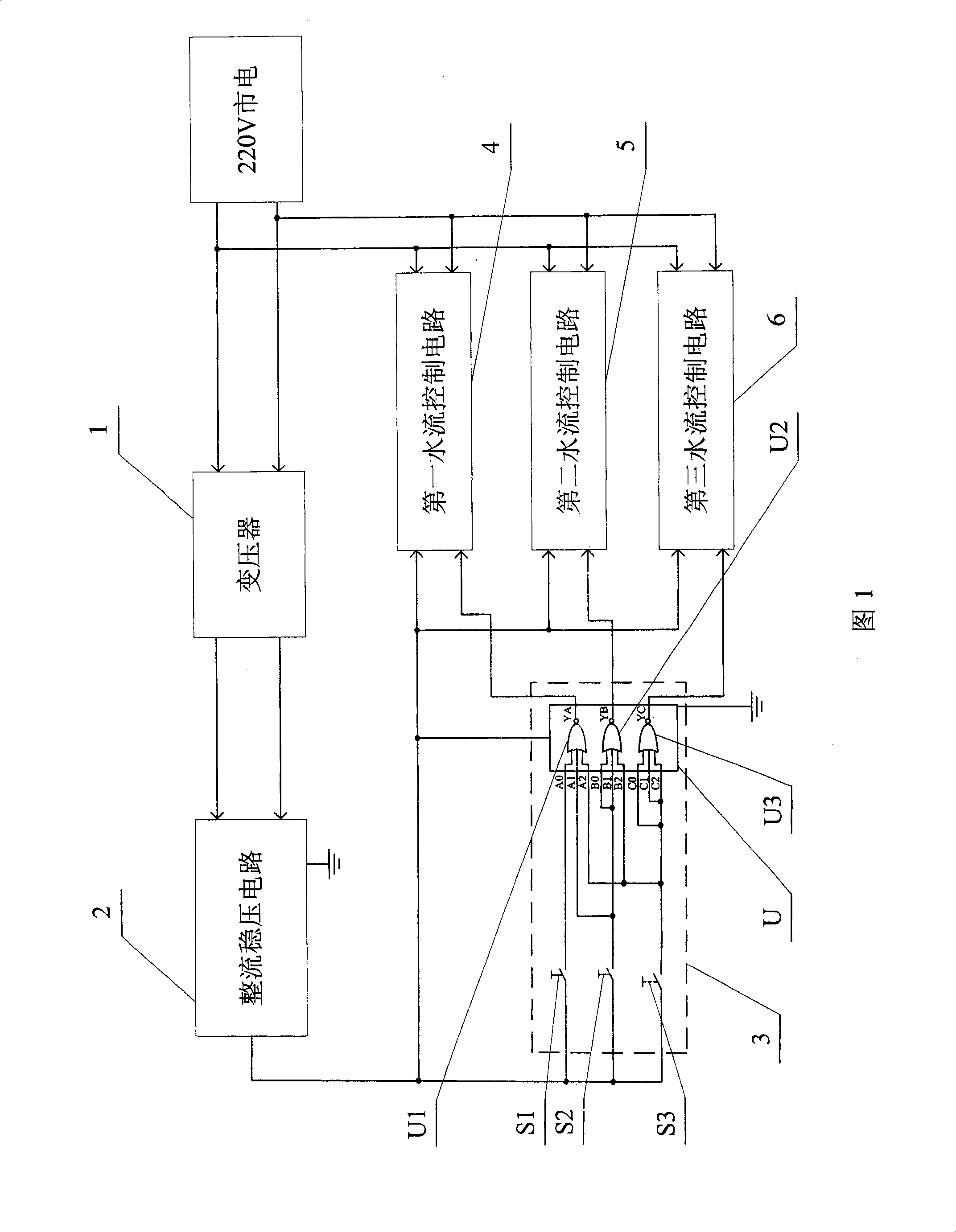
[0006] Specific embodiment 1: Referring to Fig. 1 and Fig. 5, this embodiment consists of a transformer 1, a rectification and voltage stabilization circuit 2, a logic control circuit 3, a first water flow control circuit 4, a second water flow control circuit 5, and a third water flow control circuit 6 Composition, the first power input end of transformer 1 is connected to the first end of 220V mains, the second power input end of transformer 1 is connected to the second end of 220V mains, the first power output end of transformer 1 is connected to rectified and stabilized voltage The first power supply input terminal of the circuit 2 is connected, the second power supply output terminal of the transformer 1 is connected with the second power supply input terminal of the rectification and voltage stabilization circuit 2, the first positive power supply terminal, the second positive power supply terminal, the second positive power supply terminal of the logic control circuit 3 ...

specific Embodiment approach 2

[0008] Specific embodiment two: Referring to Fig. 5, the difference between this embodiment and specific embodiment one is that the rectification and voltage stabilization circuit 2 is composed of a diode rectifier bridge B1, a first filter capacitor C1, a second filter capacitor C2 and a three-terminal voltage regulator The first power input terminal of the diode rectifier bridge B1 is connected to the first power output terminal of the transformer 1, the second power input terminal of the diode rectifier bridge B1 is connected to the second power output terminal of the transformer 1, and the diode rectifier bridge B1 The positive power supply terminal of the three-terminal voltage regulator VR1 is connected to the input terminal Vin of the three-terminal voltage regulator VR1, the negative power supply terminal of the diode rectifier bridge B1 and the ground terminal GND of the three-terminal voltage regulator VR1 are both grounded, and the input terminal Vin of the three-term...

specific Embodiment approach 3

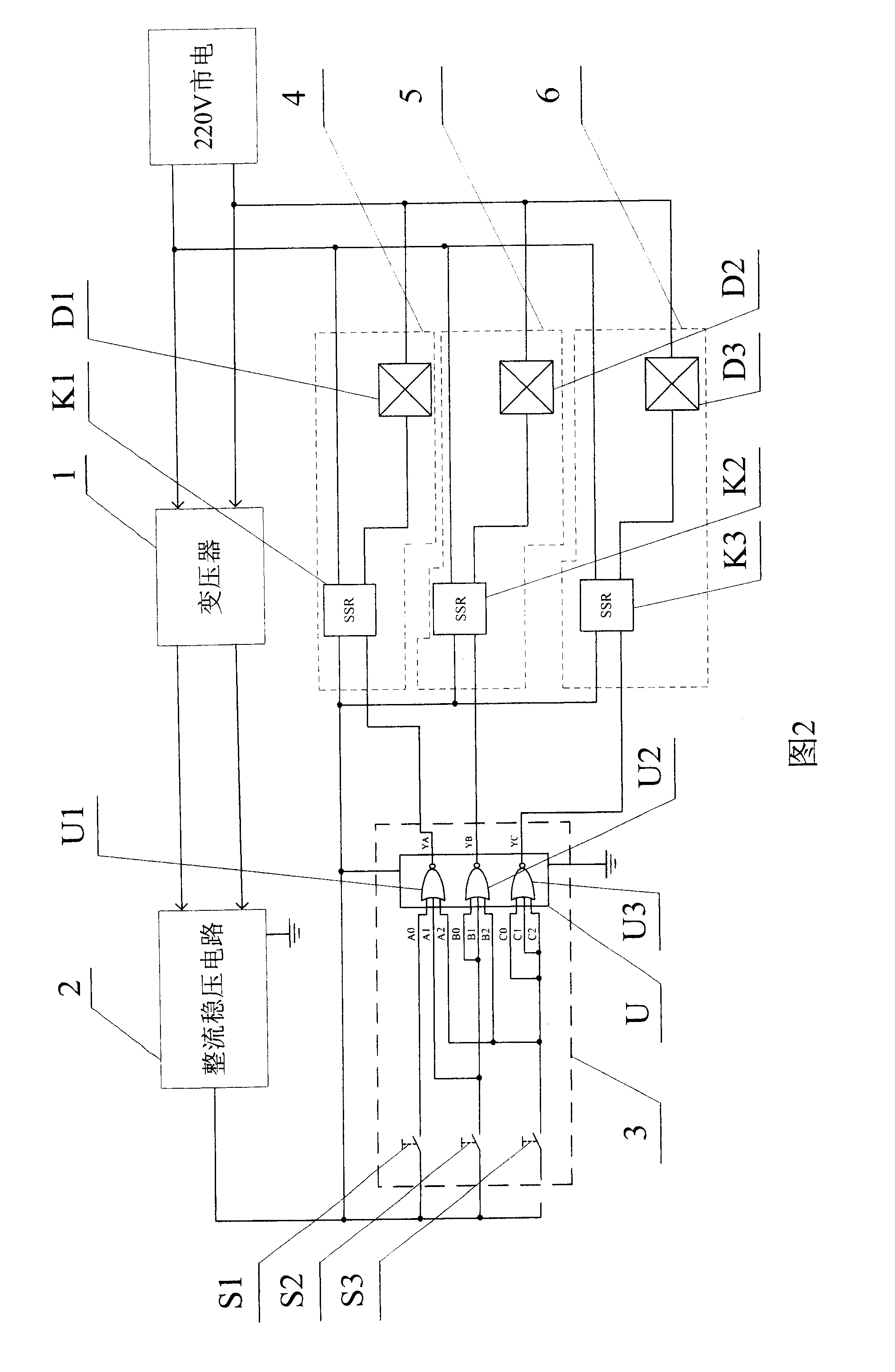
[0010] Specific embodiment three: Referring to Fig. 2, the difference between this embodiment and specific embodiment one is that the first water flow control circuit 4 includes a first solid state relay K1 and a first electromagnetic valve D1, and the first solid state relay K1 The control input terminal is connected to the first control output terminal of the logic control circuit 3, the second control input terminal of the first solid state relay K1 is connected to the positive power supply terminal of the rectification and voltage stabilization circuit 2, and the first power supply input terminal of the first solid state relay K1 Connect to the first end of 220V mains, the second power input end of the first solid state relay K1 is connected to the first power input end of the first solenoid valve D1, the second power input end of the first solenoid valve D1 is connected to the 220V mains The second end connection. Other compositions and connections are the same as in the ...


PUM


Abstract

The invention is used for solving the issue of traditional water valve that is easy to spread germ, hard to control the flow rate and hard to synchronize. In the invention, the first end of first touch-sensitive switch, second touch-sensitive switch and third touch-sensitive switch is connected to the positive power source end of the rectification stabilization circuit; the input of the first nor-gate is connected to the second end of the first touch-sensitive switch; the input of the first nor-gate and second nor-gate is connected to the second end of the second touch-sensitive switch; the input of first nor-gate, second nor-gate and third nor-gate is connected to the second end of the third touch-sensitive switch; the control input end of the first nor-gate is connected to the control input end of the first flow control circuit; the control output end of second nor-gate is connected to the control input end of the second flow control circuit; the control output end of third nor-gate is connected to the input control end of the third flow control circuit.

Description

technical field [0001] The invention relates to a device capable of synchronously controlling water discharge and having gears for adjusting water discharge. Background technique [0002] At present, in the field of water flow terminal control, two control methods are mainly used: one is the traditional manual contact water flow valve; the other is the non-contact water flow electronic control system controlled by electronic sensors. But they all have their own shortcomings: First, although the water flow controllers such as traditional faucets are convenient, they must be rotated or pressed by the user during use, resulting in unavoidable contact between the human body and the control parts, which is easy to spread germs , which affects the safety and health conditions to a certain extent; although the second type of inductive electronic control system avoids the direct contact between the human body and the water flow output equipment by using the inductive device, and sol...

Claims


Application Information

Patent Timeline
Patent Type & Authority Patents(China)
IPC IPC(8): G05D7/06
Inventor 张一凡王振中孙建鑫
Owner HARBIN INST OF TECH
Why Eureka
Try Eureka