Equipment head for lifting, transporting and placing components

A technology of structural components and assembly heads, applied in the direction of electrical components, electrical components, etc., can solve problems such as vibration of linear motors and components fixed on it, reduce mechanical vibration, maintain assembly accuracy, and increase assembly speed Effect

Inactive Publication Date: 2009-01-14
SIEMENS ELECTRONICS ASSEMBLY SYST LLC
View PDF9 Cites 0 Cited by
  • Summary
  • Abstract
  • Description
  • Claims
  • Application Information

AI Technical Summary

Problems solved by technology

Despite this elastic support of the stator, vibrations of th

Method used


Image

  • Equipment head for lifting, transporting and placing components
  • Equipment head for lifting, transporting and placing components
  • Equipment head for lifting, transporting and placing components

Examples


Embodiment Construction

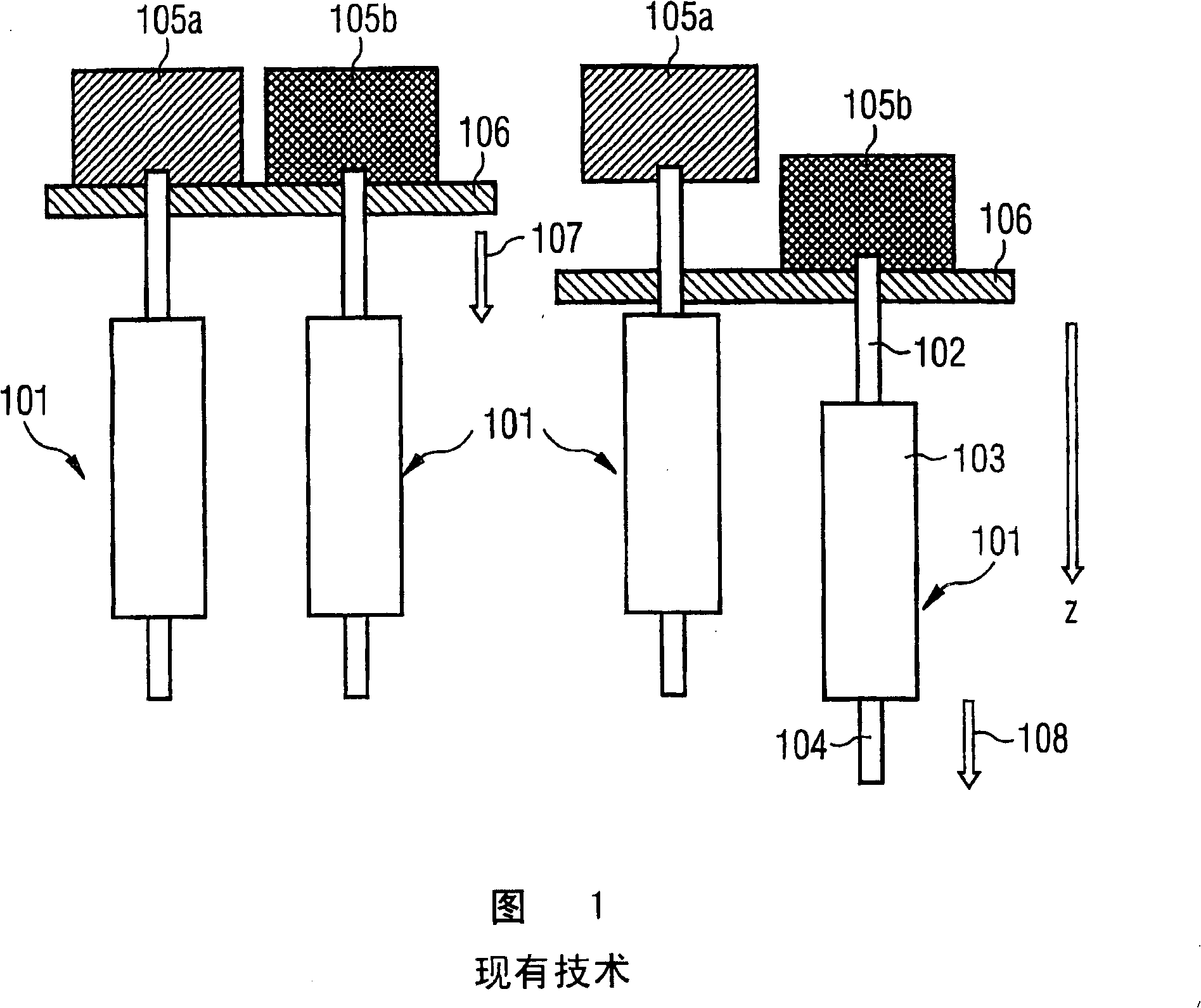
[0043] It should be noted here that the reference signs of mutually corresponding components differ only in their first digits.

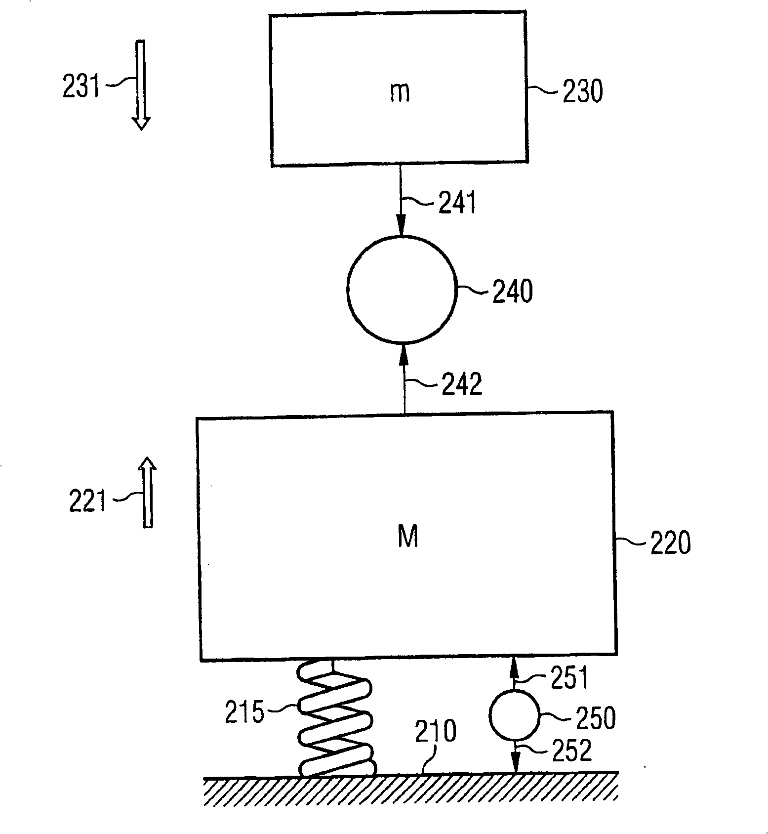
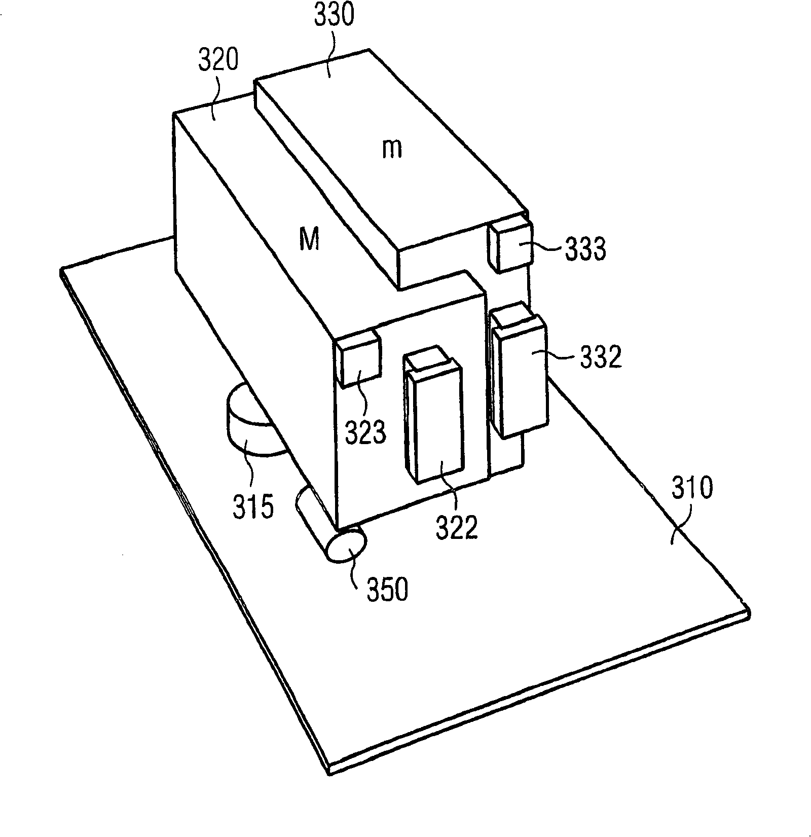
[0044] as by figure 2 As can be seen from the shown block diagram, a stator 220 of a linear motor is mechanically connected via a spring structure 215 to a base body 210 of the assembly head. In addition to the stator 220 , the linear motor also includes a mover 230 . The mechanical connection between stator 220 and mover 230 is schematically indicated by a linear drive 240 .

[0045] Next, explain the situation that the mover 230 moves downward due to the force and reaction force generated when the linear motor moves. In this case, the linear drive 240 induces a force 241 which acts on the mover 230 and pulls this downwards. Wherein, according to the principle of Newton's law that the action force and the reaction force are equal, a reaction force 242 is generated, which acts on the stator 220 and pulls it upward. Due to the force effect of the...


PUM


Abstract

The invention relates to an equipment head for lifting, transporting and placing components comprising a main body (310), a linear motor and at least one fixing device. Said linear motor comprises a stator (320) and a rotor (330). The stator (320) is resiliently mounted on the main body (310). Said rotor (330) is displaceable with respect to the stator (320) along an axis z. The fixing device is also movably mounted along said axis z and is connectable to the rotor (330). The resilient assembly of the stator (320) on the main body (310) makes it possible to reduce vibrations which are produced by impulse motion of the linear motor and transmitted to the main body. The active control of the stator (320) position by means of an adjusting drive (350) makes it possible to maintain the centre of gravity of the linear motor. The control of said adjusting device is carried out by means of distance transducers (323, 333) which detect the displacements of the stator (320) and of the rotor (330) with respect to the main body (310).

Description

technical field [0001] The invention relates to an assembly head for receiving structural elements from a structural element feeder, conveying the received structural elements to an assembly station and placing the structural elements on a structural element carrier. Background technique [0002] In general, the equipping of the structural element carrier takes place on so-called automatic assembly machines. In this case, the structural elements are received by an assembly head from a structural element delivery device, transported to the structural element carrier to be equipped and placed on the structural element carrier at a predetermined assembly station. In order to achieve a high assembly efficiency, assembly heads are used, which have a plurality of support devices, so that during the extraction process, several structural elements can be successively received and these received structural elements can be successively placed on the corresponding prefabricated parts. ...

Claims


Application Information

Patent Timeline
IPC IPC(8): H05K13/04
CPCH05K13/0413H05K13/0406
Inventor S·布格尔
Owner SIEMENS ELECTRONICS ASSEMBLY SYST LLC
Why Eureka
Try Eureka