Control circuit for power converter with adaptive bias

A technology of power converters and control circuits, applied in the direction of output power conversion devices, control/regulation systems, instruments, etc.

Inactive Publication Date: 2009-01-21
SYST GEN
View PDF6 Cites 9 Cited by
  • Summary
  • Abstract
  • Description
  • Claims
  • Application Information

AI Technical Summary

Problems solved by technology

However, the parasitic capacitor 23 and resistor 22 will contribute to the reflected voltage V F Produces the effect of low-pass filtering

Method used


Image

  • Control circuit for power converter with adaptive bias
  • Control circuit for power converter with adaptive bias
  • Control circuit for power converter with adaptive bias

Examples


Embodiment Construction

[0018] The features and functions of the control circuit of the power converter according to the present invention will be described in detail below with reference to the accompanying drawings and preferred embodiments.

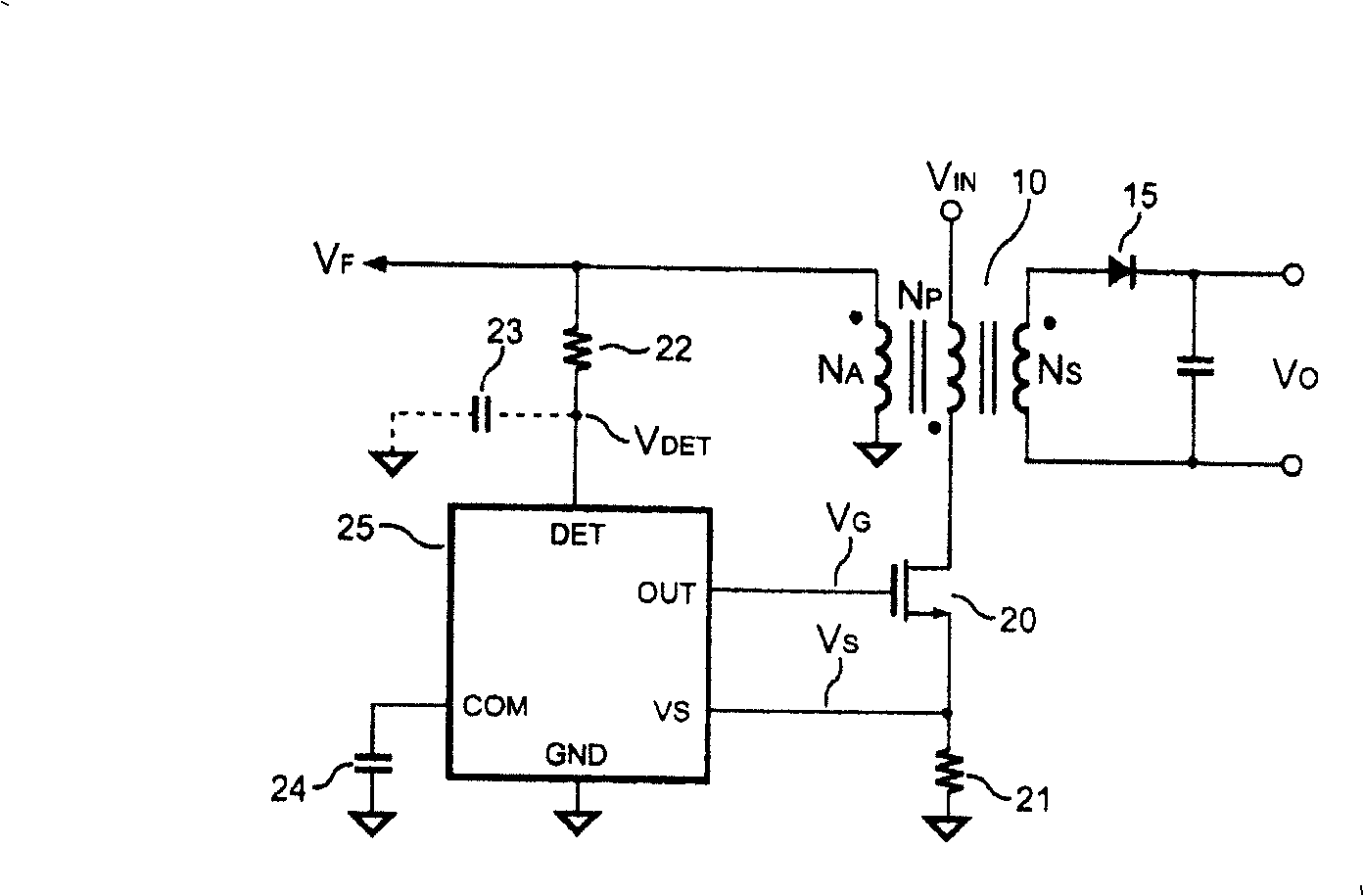
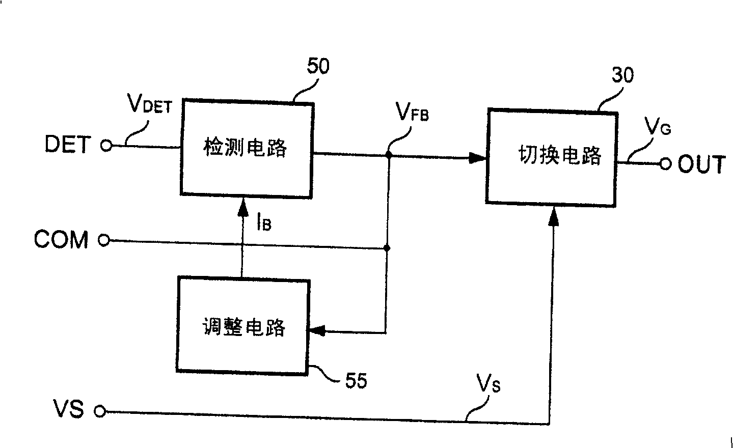
[0019] Please refer to figure 1 , the control circuit of the power converter includes a switch 20 and a controller 25 . The controller 25 generates a control signal V G To control the switch for switching the transformer 10. image 3 A block diagram of a controller 25 according to an embodiment of the present invention is shown. The controller 25 includes a switch circuit 30 , a detection circuit 50 , and an adjustment circuit 55 . refer to figure 1 , the detection circuit 50 is coupled to the transformer 10 to detect the reflected voltage V of the transformer 10 F , and according to the reflected voltage V F Generates a feedback signal V FB . The switching circuit 30 generates the control signal V at the output of the controller 25 G , and according...


PUM


Abstract

The invention discloses control circuit for detecting reflected voltage of transformer. The detecting circuit is in use for sampling reflected voltage. Since pulse width of reflected voltage is narrower under state of light load, thus, using biasing circuit generates biasing signal to help to detect reflected voltage. Besides, blanking circuit ensures minimum pulse width of reflected voltage.

Description

technical field [0001] The present invention relates to a power converter, and more particularly, the present invention relates to a switching power converter. Background technique [0002] Power converters are widely used to provide stable and regulated outputs. For safety reasons, power converters must provide galvanic isolation between their primary and secondary sides. Typically, transformers are used to provide isolation and energy transfer. figure 1 A conventional power converter with transformer 10 is shown. Energy is stored inside the transformer 10 when the switch 20 is turned on. When the switch 20 is open, energy will be released to the output of the power converter. A resistor 21 is connected in series with the switch 20 to sense the switching current of the transformer 10 and generate a current signal V for switching control S . The controller 25 is coupled to the transformer 10 and the resistor 21 to generate the control signal V G , so as to control the...

Claims


Application Information

Patent Timeline
Patent Type & Authority Patents(China)
IPC IPC(8): H02M3/335G05F1/565
Inventor 杨大勇李俊庆曹峰诚
Owner SYST GEN
Why Eureka
Try Eureka