Multi-input differential circuit

a multi-input, differential amplifier technology, applied in the direction of pulse manipulation, electrical apparatus, pulse technique, etc., to achieve the effect of reducing the idling current, simple design theory, and less transistor coun

Inactive Publication Date: 2005-01-27
NANOPOWER SOLUTION
View PDF15 Cites 9 Cited by
  • Summary
  • Abstract
  • Description
  • Claims
  • Application Information

AI Technical Summary

Problems solved by technology

Therefore it is presumable that boosted operation current only at the detection transition will realize low power and high-speed circuit, however no prior proposal attains the goal with less transistor count and simple design theory.

Method used


Image

  • Multi-input differential circuit
  • Multi-input differential circuit
  • Multi-input differential circuit

Examples


embodiment

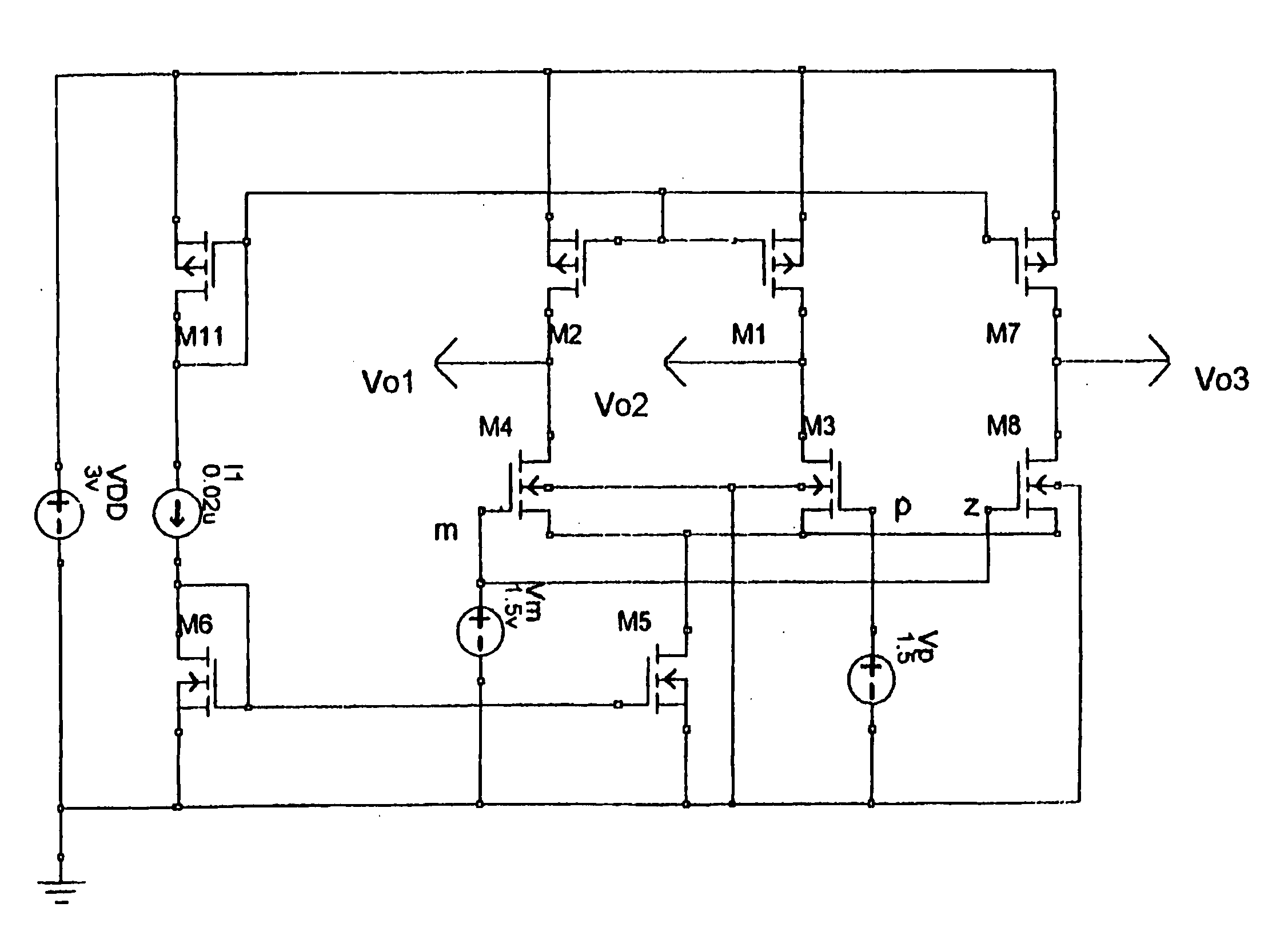
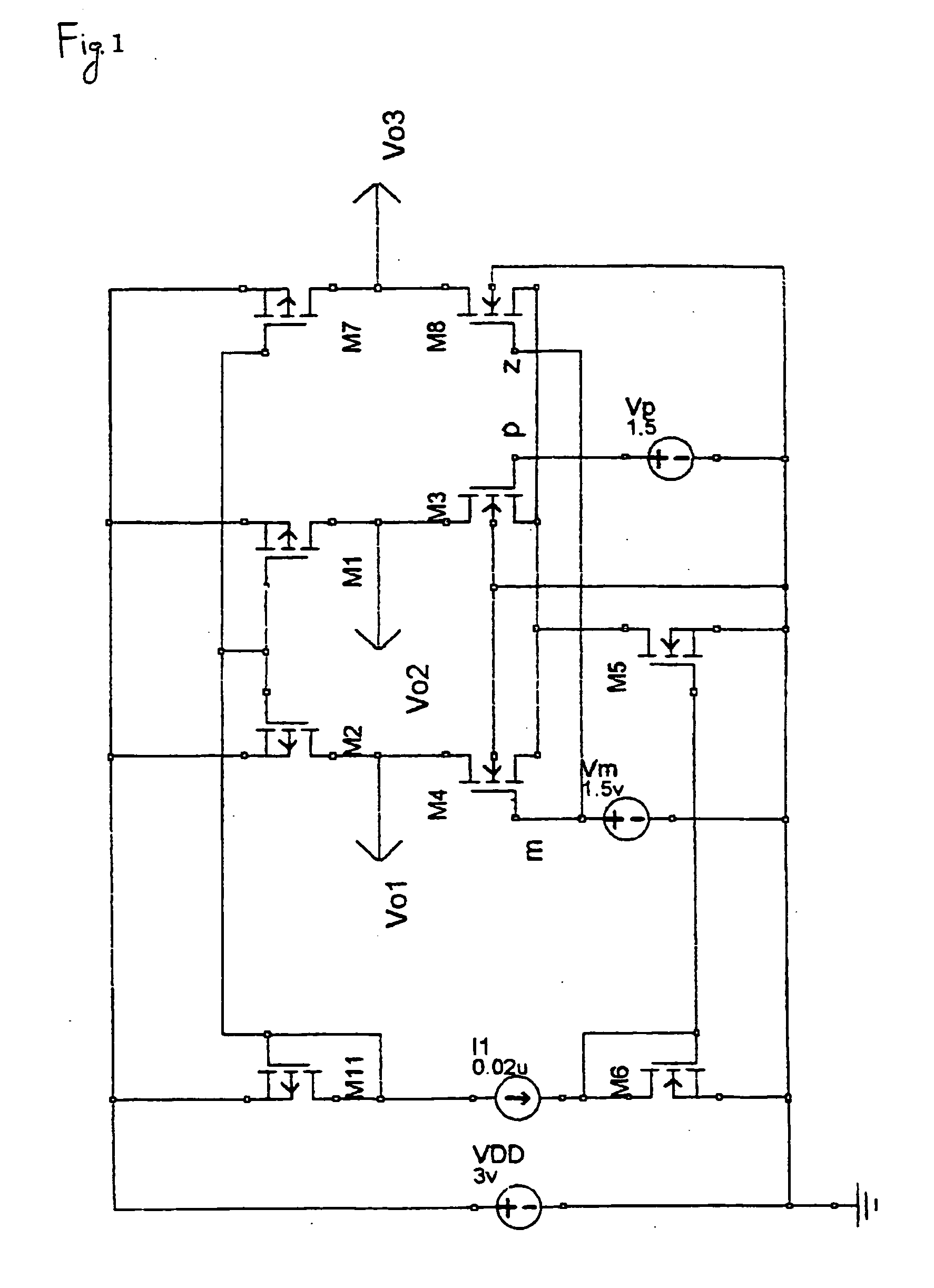
In FIG. 1, the bias current control circuit M5 has important roll. It is not restricted one component; more parts form it as described later. The present invention disclose that three amplifiers act each other in the range of the size of M5 or the mirror current of bias current control circuit and a boundary condition is discovered successfully.

Hereinafter, a total sum of FET means a summing size of FETs connected in parallel way.

And a theoretical mirror current means a mirrored current under no obstacle to mirror operation. Usually the mirror current is proportional to transistor size.

In the figure when the size of M5 is larger than the sum of FET size M1, M2 and M7 or the theoretical mirror current of the bias current control circuit is larger than the total sum of mirror current of M1, M2 and M7, the circuit in FIG. 1 is not functional. The tail node is shorted to ground level; the three amplifiers have no interaction each other.

When the theoretical mirror current of the...


PUM


Abstract

The invention provides a NANO-ampere operable differential circuit by means of a few additional components. The multi-input differential circuit consists of more than three input elements that are connected to the same tail node, and an adaptive bias current control circuit. Applications of this multi-input differential circuit, which are, for instance comparators and voltage followers, do have a very low operation current at a normal operation mode. The proposed differential circuit is applicable for all kinds of analog complex circuits to attain nano-power operation.

Description

BACKGROUND OF THE INVENTION The present invention relates to an over-three multi-input differential amplifier with adaptively controlled biasing. 1. Description of the Related Art Not only handy equipment but also every kind of electric equipment incorporates a voltage comparator circuit or differential amplifier applied for low voltage detection or battery charge-discharge control or signal buffering. It is assumed that a few billion of such equipments. are in use worldwide. If one comparator circuit draws 10 μA for example, the total idling current is multiplied by 10 billion sets and 10,000 ampere is given. If an operation voltage is assumed at 5 volt, the total power consumption reaches 50 KILO-watt what is equivalent to one power plant capacity. The present invention will reduce current consumption of a voltage comparator and differential amplifier drastically to contribute to energy saving on a global scale. 2. Description of the Prior Art FIG. 18 shows a conventional prio...

Claims


Application Information

Patent Timeline
Patent Type & Authority Applications(United States)
IPC IPC(8): H03F3/45H03F1/02H03K5/24
CPCH03F2203/45352H03K5/2481H03F2203/45454
Inventor AKITA, SHIN-ICHIIKURA, YASUHIDEYANO, TATSUHIRO
Owner NANOPOWER SOLUTION
Why Eureka
Try Eureka