Adaptive bias current generator methods and Apparatus

a bias current and generator technology, applied in the direction of automatic control, process and machine control, instruments, etc., can solve the problems of circuits with sub-optimal power consumption, a/d converters dissipating more power than required, and electronic devices dissipating excess power, so as to reduce power consumption in circuits

Active Publication Date: 2008-11-20
ANALOG DEVICES INC
View PDF4 Cites 10 Cited by
  • Summary
  • Abstract
  • Description
  • Claims
  • Application Information

AI Technical Summary

Benefits of technology

[0008]Some embodiments include a method of reducing power consumption in a circuit by adaptive bias current generation of a bias current configured to bias, at least in part, at least one amplifier of the circuit, the method comprising establishing the bias current based, at least in part, on a capacitance of a reference capacitor, and changing the bias current in response to a change in the capacitance of the reference capacitor such that the bias current is changed non-linearly with respect to changes in the capacitance of the reference capacitor.

Problems solved by technology

As a result, the A / D converter dissipates more power than required whenever it operates at less than the maximum operating speed.
As a result, the electronic device will dissipate excess power under such conditions.
Accordingly, such circuits will have sub-optimal power consumption when implemented with constant bias currents.
Manufacture of electronic components and / or fabrication of a circuit or device will often cause the operating parameters of the electronic components to deviate from their nominal value, and also deviate from fabrication to fabrication.

Method used


Image

  • Adaptive bias current generator methods and Apparatus
  • Adaptive bias current generator methods and Apparatus
  • Adaptive bias current generator methods and Apparatus

Examples


Embodiment Construction

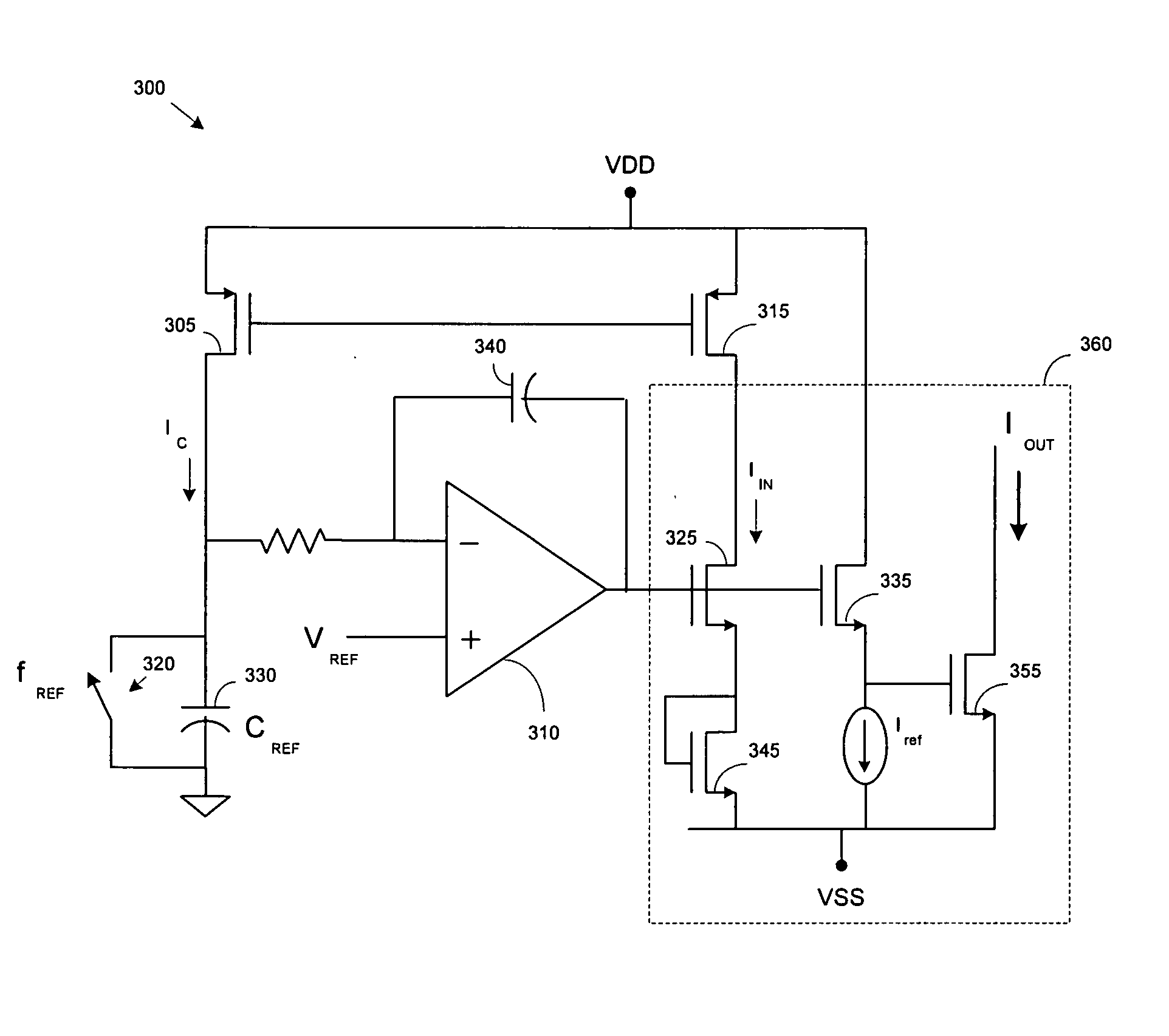
[0016]A / D converters are often built with a number of amplifiers, which are in turn biased with current reference circuits. The bias current of an amplifier is related to the bandwidth of the amplifier; the larger the bias current, the wider the bandwidth. The settling time of an amplifier is proportional to the bandwidth of the amplifier. As a result, bias current implicates an amplifier settles, and therefore how fast the A / D converter may operate. For example, an amplifier might require high bias current for the maximum sample rate, but the bias current could be reduced for lower sample rates. However, many conventional A / D converters maintain the bias current necessary to achieve the maximum required operating speeds (e.g., the maximum sample rate required of the A / D converter). Accordingly, when the A / D converter is operating at lower operating speeds, the bias current is unnecessarily high, resulting is excess power dissipation.

[0017]Applicant has appreciated that by varying t...


PUM

PropertyMeasurementUnit
power consumptionaaaaaaaaaa
reference frequencyaaaaaaaaaa
frequencyaaaaaaaaaa

Abstract

In one aspect, a method of reducing power consumption in a circuit by adaptive bias current generation of a bias current configured to bias, at least in part, at least one amplifier of the circuit is provided. The method comprises establishing the bias current based, at least in part, on a reference frequency of a reference clock providing a clock signal to at least one component of the circuit, and changing the bias current in response to a change in the reference frequency of the at least one reference clock, the bias current being change non-linearly with respect to the change in the reference frequency of the at least one reference clock. In another aspect, the method comprises establishing the bias current based, at least in part, on a capacitance of a reference capacitor, and changing the bias current in response to a change in the capacitance of the reference capacitor such that the bias current is changed non-linearly with respect to changes in the capacitance of the reference capacitor.

Description

RELATED APPLICATIONS [0001]This application claims the benefit under 35 U.S.C. §119(e) of U.S. Provisional Application 60 / 930,893, filed May 18, 2007, entitled “NON-LINEAR ADAPTIVE BIAS GENERATION TECHNIQUES,” by Kapusta, which is herein incorporated by reference in its entirety.FIELD OF THE INVENTION [0002]The present disclosure is directed to bias current generation, and more particularly, to bias currents generated to bias one or more amplifiers.BACKGROUND OF THE INVENTION [0003]Many electronic devices rely on analog-to-digital (A / D) converters to convert an analog signal into a digital signal. Some applications may require different conversion speeds for the same A / D converter. For example, an A / D converter integrated in a digital camera may be required to operate at different speeds depending on the mode of the camera. When the digital camera is operating in high resolution mode, the A / D converter may be required to operate at a higher sample rate than when the digital camera i...

Claims


Application Information

Patent Timeline
Patent Type & Authority Applications(United States)
IPC IPC(8): H02J1/00
CPCH03F1/0261H03F3/45183H03F3/45475H03F2200/297
Inventor KAPUSTA, JR., RONALD A.
Owner ANALOG DEVICES INC
Why Eureka
Try Eureka