Network processing device and method
A technology of network processing and processing method, applied in the field of network processing units, can solve the problems of increasing the delay of interface data reaching the micro-engine, increasing the management complexity of storage units, reducing the performance of network processing units, etc. Effects of processing performance
- Summary
- Abstract
- Description
- Claims
- Application Information
AI Technical Summary
Problems solved by technology
Method used
Image
Examples
Embodiment 1
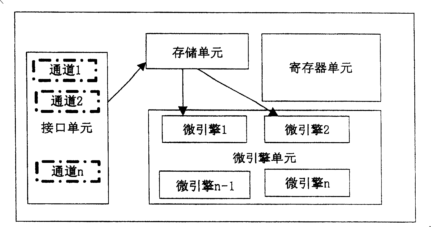
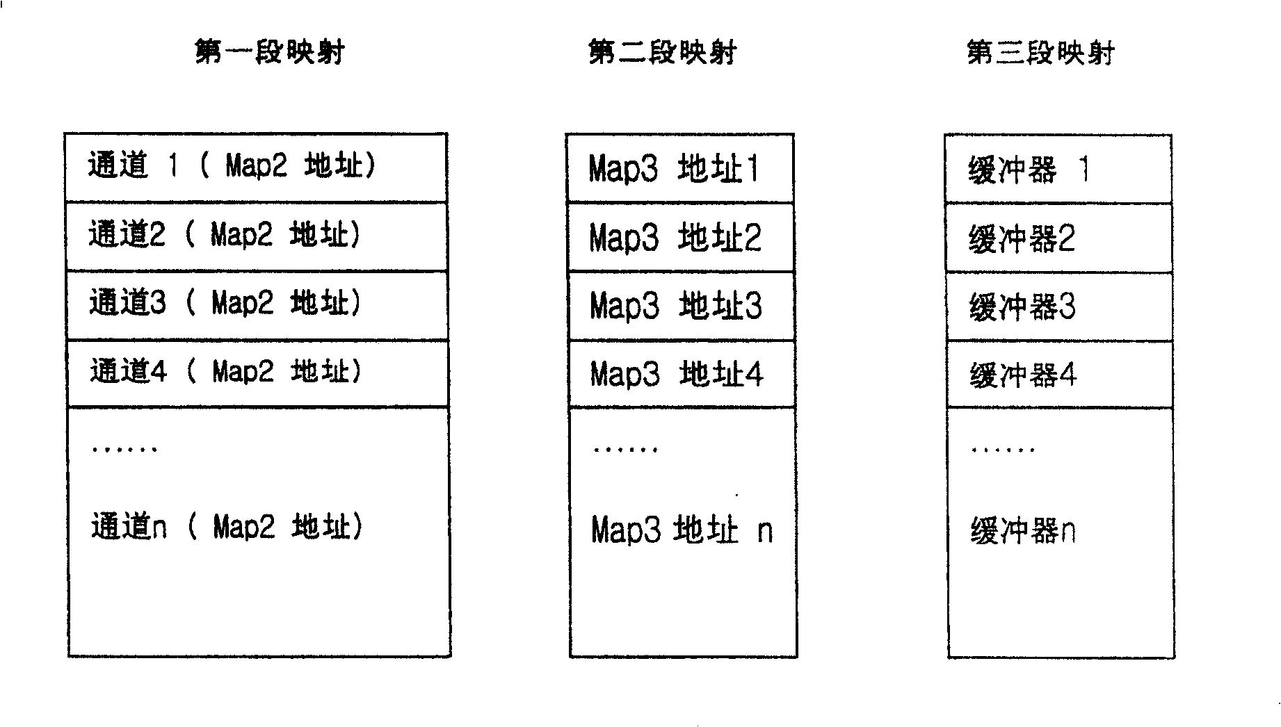
[0044] The address mapping settings of each stage are as shown image 3 As shown, the schematic diagram of its structure is shown in Figure 6 As shown, the network processing device 100 includes: an interface unit 101, a microengine unit 103, the interface unit includes a plurality of channels for receiving and forwarding messages; the microengine unit includes a plurality of microengines, The feature is that the device also includes: an address mapping unit 102, which is composed of a plurality of register segments, and is used for address mapping of segments; wherein, the messages in the channel are segmented according to the addresses of the address mapping unit Mappings are populated into the microengine's cache. Its specific mapping relationship is:
[0045] The n channel addresses of MAP Stage1 are all set to point to the address 0 of MAP Stage2, indicating that the n channels of the interface unit are valid, and messages may arrive in all of them. The 0 address of M...
Embodiment 2
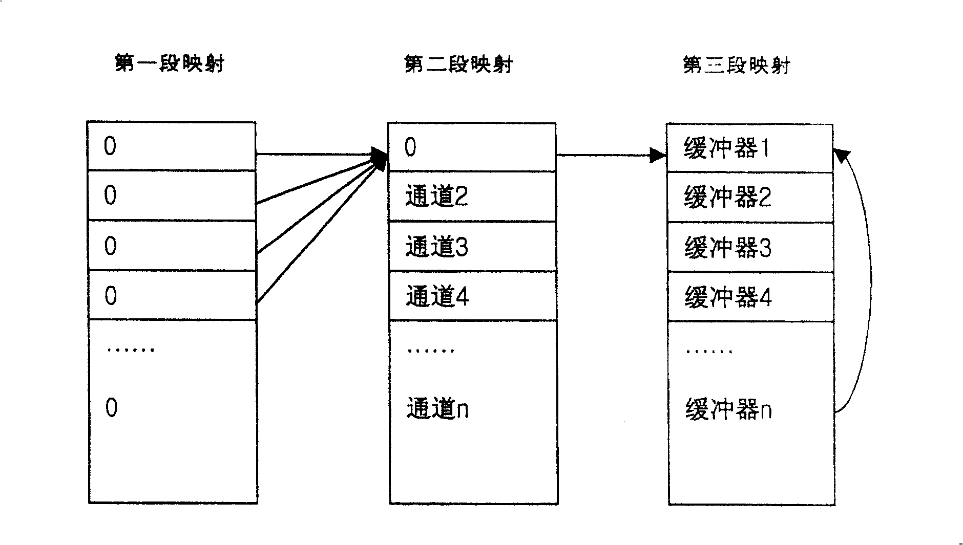
[0050] The address mapping settings of each stage are as shown Figure 4 As shown, the schematic diagram of its structure is shown in Figure 6 As shown, the network processing device 100 includes: an interface unit 101, a microengine unit 103, the interface unit includes a plurality of channels for receiving and forwarding messages; the microengine unit includes a plurality of microengines, The feature is that the device also includes: an address mapping unit 102, which is composed of a plurality of register segments, and is used for address mapping of segments; wherein, the messages in the channel are segmented according to the addresses of the address mapping unit Mappings are populated into the microengine's cache. Its specific mapping relationship is:
[0051] The n channels of the MAP Stage1 address are all set to point to the value of the MAP Stage2 address, and the n channels of the MAP Stage1 address are all valid. The value set by channel 1 points to MAP Stage2 ad...
Embodiment 3
[0056] The address mapping settings of each stage are as shown Figure 5 As shown, the schematic diagram of its structure is shown in Figure 6 As shown, the network processing device 100 includes: an interface unit 101, a microengine unit 103, the interface unit includes a plurality of channels for receiving and forwarding messages; the microengine unit includes a plurality of microengines, The feature is that the device also includes: an address mapping unit 102, which is composed of a plurality of register segments, and is used for address mapping of segments; wherein, the messages in the channel are segmented according to the addresses of the address mapping unit Mappings are populated into the microengine's cache. Its specific mapping relationship is:
[0057]The two channel addresses of MAP Stage1 are set to point to MAP Stage2 address 0, the other two channel addresses of MAP Stage1 are set to point to MAP Stage2 address 3 and address 4 respectively, and the remaining...
PUM
 Abstract
Description
Claims
Application Information
 - R&D
- Intellectual Property
- Life Sciences
- Materials
- Tech Scout
- Unparalleled Data Quality
- Higher Quality Content
- 60% Fewer Hallucinations
Browse by: Latest US Patents, China's latest patents, Technical Efficacy Thesaurus, Application Domain, Technology Topic, Popular Technical Reports.
© 2025 PatSnap. All rights reserved.Legal|Privacy policy|Modern Slavery Act Transparency Statement|Sitemap|About US| Contact US: help@patsnap.com


