Igniter device for discharge lamp

A technology for lighting devices and discharge lamps, which is applied to discharge lamps, electric lamp circuit layout, lighting devices, etc., and can solve the problems of fluorescent lamps flashing and lighting circuits malfunctioning, etc.

Inactive Publication Date: 2009-03-04
PANASONIC CORP
View PDF3 Cites 0 Cited by
  • Summary
  • Abstract
  • Description
  • Claims
  • Application Information

AI Technical Summary

Problems solved by technology

In addition, there are also problems such as malfunction of the lighting circuit and fluorescent lamp flashing.

Method used


Image

  • Igniter device for discharge lamp
  • Igniter device for discharge lamp
  • Igniter device for discharge lamp

Examples


Embodiment 1

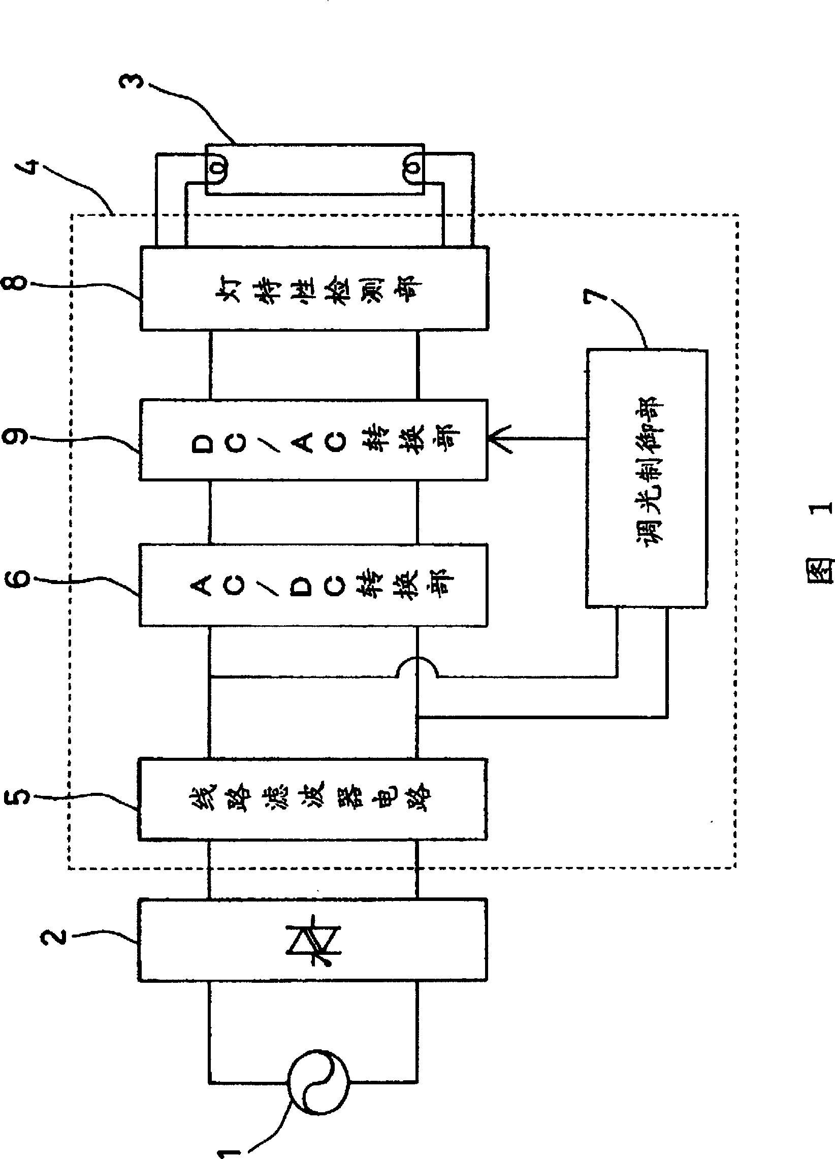
[0021] Fig. 1 shows the configuration of a discharge lamp lighting device in Embodiment 1 of the present invention. 1 is an AC power supply that outputs an AC voltage, for example, a 60Hz, 100V power supply. 2 is a dimmer, which controls the phase of AC voltage 1 . As the dimmer 2, a known dimmer including a triac or the like can be used. 3 is a fluorescent lamp as a discharge lamp, and 4 is a lighting circuit for supplying power to the fluorescent lamp 3 and lighting the fluorescent lamp.

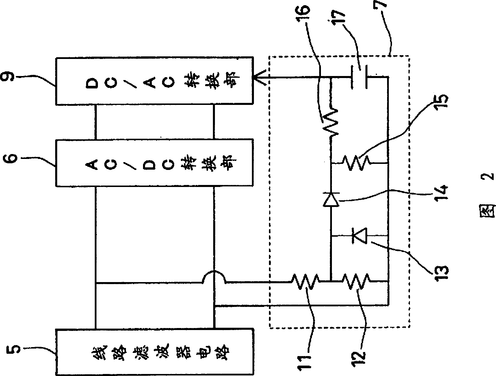
[0022] The lighting circuit 4 is composed of a line filter 5 , an AC / DC conversion unit 6 , a dimming control unit 7 , a DC / AC conversion unit 9 , and a lamp characteristic detection unit 8 . The line filter 5 is composed of an inductance element, a capacitor, etc., and prevents high-frequency noise from the AC power supply 1 . The AC / DC converter 6 is a component for converting the phase-controlled AC voltage output from the dimmer 2 into a DC voltage, and is composed of a rectifier ci...

Embodiment 2

[0035] Figure 5 The configuration of the discharge lamp lighting device in Embodiment 2 of the present invention is shown. Figure 5 Among them, 51 is a curved fluorescent lamp as a discharge lamp, and 52 is a base such as an E26 type for an incandescent light bulb. 53 is a circuit board, and each circuit part 56 that constitutes the same lighting device as the embodiment 1 shown in Fig. 1 is installed. 54 is a cover, and a lamp cap 52 is installed at one end, and the circuit board 53 is accommodated inside. 55 is a sphere with light transmission characteristics, covering the periphery of the fluorescent lamp 51 and placing it.

[0036] The fluorescent lamp 51 is electrically connected to the circuit board 53 , and the circuit board 53 and the cap 52 are not shown in the figure, and the cap 52 is screwed into a socket for an incandescent bulb to supply power to light the fluorescent lamp 51 . The AC voltage input through the base 52 is an AC voltage whose phase is controlle...


PUM


Abstract

A ballast for a discharge lamp includes a fluorescent lamp (3), an AC / DC conversion portion (6), a dimming control portion (7), and a DC / AC conversion portion (9). The AC / DC conversion portion (6) converts a phase-controlled input AC voltage to a DC voltage. The dimming control portion (7) calculates a dimming control signal from the input AC voltage. The DC / AC conversion portion (9) converts the DC voltage from the AC / DC conversion portion (6) to a high frequency AC voltage to be applied to the fluorescent lamp (3) and lights and dims the lamp in response to the dimming control signal. The DC / AC conversion portion has a first operation mode for maintaining the lighting of the fluorescent lamp and for lighting and dimming the same and a second operation mode for supplying the fluorescent lamp with a voltage lower than the starting voltage of the lamp in its non-operating state. The conducting period of the phase-controlled AC voltage can be detected even in the non-operating state of the fluorescent lamp so as to restart the lamp.

Description

field of invention [0001] The present invention relates to a discharge lamp for inputting an AC voltage for phase control, and more specifically, to a discharge lamp lighting device for dimming and lighting a fluorescent lamp. Background of the invention [0002] Compared with incandescent light bulbs, fluorescent lamps have the characteristics of high efficiency and long life, and are widely used mainly for home lighting. In particular, a bulb-shaped fluorescent lamp in which a fluorescent lamp and a high-frequency inverter are integrally formed can be mounted in a socket for an incandescent light bulb as it is, thereby expanding its use from the viewpoint of saving energy and resources. [0003] However, in recent years, as the desire to dim light bulb-shaped fluorescent lamps similarly to that of incandescent bulbs has increased, dimmable light bulb-shaped fluorescent lamps have been developed. The dimming of an incandescent light bulb is generally a method of using a di...

Claims


Application Information

Patent Timeline
Patent Type & Authority Patents(China)
IPC IPC(8): H05B41/392H05B41/295H05B41/24H05B37/02
CPCH05B41/3925H05B37/0263H05B41/3921Y10S315/04H05B41/3924H05B47/185
Inventor 小南智高桥健一郎业天正芳宫崎光治
Owner PANASONIC CORP
Why Eureka
Try Eureka