Cold accumulating device by ice

An ice cold storage and ice storage technology, which is applied to household refrigeration devices, lighting and heating equipment, household appliances, etc., can solve the problem of complex structure of ice-melting ice-storage cylinders, insufficient use of swirling flow enhanced heat transfer technology, and insufficient improvement of melting Ice efficiency and other issues, to avoid excessive operating pressure, improve ice melting efficiency, and compact structure

Active Publication Date: 2009-03-11
GUANGDONG CHIGO AIR CONDITIONING
View PDF6 Cites 0 Cited by
  • Summary
  • Abstract
  • Description
  • Claims
  • Application Information

AI Technical Summary

Problems solved by technology

However, the sleeve-type inner and outer ice-melting ice-storage cylinder disclosed in the No. 200420017434 patent has a complex structure, and does not fully utilize the swirling flow enhanced heat transfer technology, so the ice-melting efficiency is still not fully improved.

Method used


Image

  • Cold accumulating device by ice
  • Cold accumulating device by ice
  • Cold accumulating device by ice

Examples


Embodiment 1

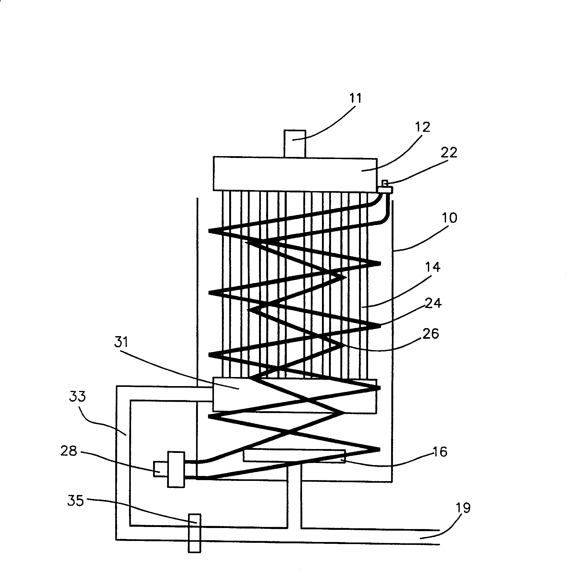
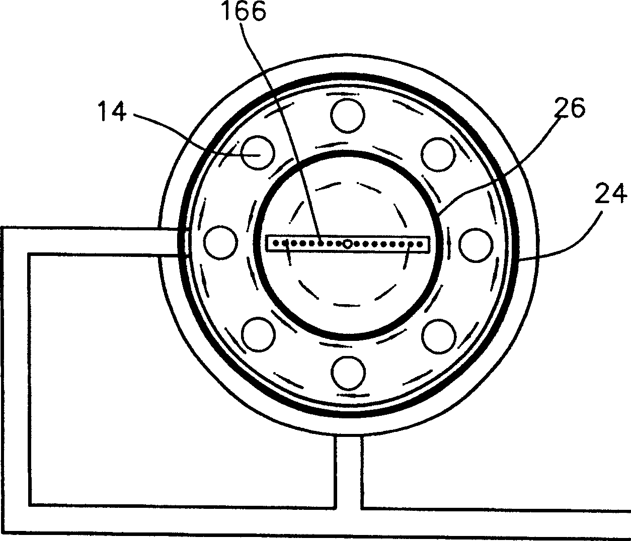
[0040] The ice cold storage device of the present invention is used for ice cold storage of an air-conditioning system to realize off-peak power consumption, and mainly includes an ice melting mechanism, an ice making mechanism, and an ice melting bypass mechanism. Among them, the ice-melting mechanism includes an ice storage cylinder 10, a water inlet 11, an upper header 12, eight ice-melting pipes 14, a water collection pipe 16, and a water supply port 19; the ice-making mechanism includes a coolant inlet 22, two ice-making pipes 24 and 26, and the coolant outlet 28; the ice-melting bypass mechanism includes a lower header 31, a bypass pipe 33, and a solenoid valve 35.

[0041] An ice storage space is formed inside the ice storage cylinder 10, and ice (in this embodiment, ice) that can solidify into a medium under the action of the coolant is injected into the ice storage space of the ice storage cylinder 10 at night when electricity consumption is low. medium (water in this...

Embodiment 2

[0052] As an optional implementation of the present invention, in this embodiment, the ice storage device can be used for ice storage in a freezer or a freezer.

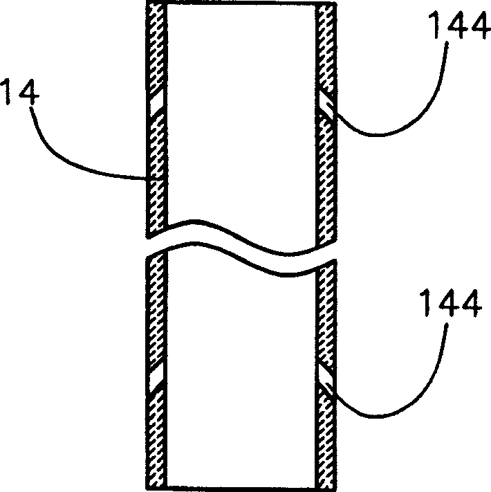
[0053] Alternatively, a row of water injection holes can only be opened on the wall of each ice-melting pipeline 14 facing the axis of the ice storage cylinder 10, and each ice-melting pipeline 14 faces the axis of the ice storage cylinder 10. Between one side of the line and the medium ice (that is, between the inner wall of the virtual cylinder and the ice) both counterclockwise and clockwise vortices can be formed.

[0054] Alternatively, a row of water injection holes 14 may also be provided only on the tube wall on the side away from the axis line of the ice storage cylinder 10, and each ice-melting pipeline 14 is away from the axis line of the ice storage cylinder 10. Between the side and the medium ice (that is, between the outer wall of the virtual cylinder and the ice) both a clockwise vortex and a countercl...


PUM


Abstract

The invention discloses an ice storage arrangement, which comprises an ice storage tube, at least one ice-making pipe, and at least 3 ice-melting pipes. The ice-making pipe and the ice-melting pipes are arranged in the ice storage tube. Wherein, on each ice-melting pipe, a row of water-jetting holes are provided on the pipe wall facing the axial line of the ice storage tube and / or on the pipe wall departing from the axial line of the ice storage tube; each row of water-jetting holes comprise at least 10 downward tilting water-jetting holes that are distributed along the axial direction of the ice-melting pipe; the water in the ice-melting pipes jets through the water-jetting holes into the ice storage tube to form CW and / or CCW vortex; it is preferably that the included angle between the opening direction of each water-jetting hole and the section of the ice-melting pipe is 30-60 degree; and it is even more preferably that the ice storage arrangement further comprises an ice-melting bypass mechanism, which comprises a lower collecting box communicated with the lower end of the ice-melting pipe, a bypass pipe and a solenoid valve for turning on / off the bypass pipe, wherein, the bypass pipe is communicated with the lower collecting box and a water supply port.

Description

technical field [0001] The invention relates to an ice cold storage device, in particular to a direct contact swirl ice-melting cold storage device. Background technique [0002] Cold storage technology is a practical and comprehensive technology emerging to realize peak shifting and valley filling of the power grid. In developed countries, due to the active encouragement and advocacy of various power companies and government energy departments, the cold storage technology has been continuously improved and matured, and its popularization and application has been developed rapidly. With the continuous development of our country's economy, the gap between peak and valley power supply in cities and towns continues to increase. In order to ensure the sustainable, stable and rapid development of the national economy, improve and alleviate the tension in power supply, the State Planning Commission and the power department have made Short-term and long-term planning requirements ...

Claims


Application Information

Patent Timeline
Patent Type & Authority Patents(China)
IPC IPC(8): F25D3/02
Inventor 陈颖刘效洲
Owner GUANGDONG CHIGO AIR CONDITIONING
Why Eureka
Try Eureka