Diffusion sheet, surface light source device and transmission display unit

A technology of diffuser plate and surface light source, which is applied to electric light sources, lighting devices, components of lighting devices, etc., can solve the problems of increased cost, convergence of emitted light, and reduced light utilization efficiency, and achieves the effect of improving and reducing unevenness. Improve the effect of reducing unevenness and improving utilization efficiency

Active Publication Date: 2009-03-11
DAI NIPPON PRINTING CO LTD
View PDF13 Cites 0 Cited by
  • Summary
  • Abstract
  • Description
  • Claims
  • Application Information

AI Technical Summary

Problems solved by technology

However, in such a conventional direct-type surface light source device, there is a problem that there are too many optical plates required, and the light-converging characteristics are relatively insufficient. In order to compensate for this deficiency, transmissive displays such as LCD panels have been improved. The structure of the part itself, so that the incident light from an oblique direction will not reduce the image quality
However, in this conventional method, there are problems in that the utilization efficiency of light is lowered, and the structure of a transmissive display portion such as an LCD panel becomes complicated, resulting in an increase in cost.
Therefore, especially for the light transmitted after total reflection, it emerges from the plate at a relatively large exit angle, and the exit light spreads in a wider range, and there is a problem that it is difficult to converge the exit light to the required exit angle range.

Method used


Image

  • Diffusion sheet, surface light source device and transmission display unit
  • Diffusion sheet, surface light source device and transmission display unit
  • Diffusion sheet, surface light source device and transmission display unit

Examples


Embodiment Construction

[0032]

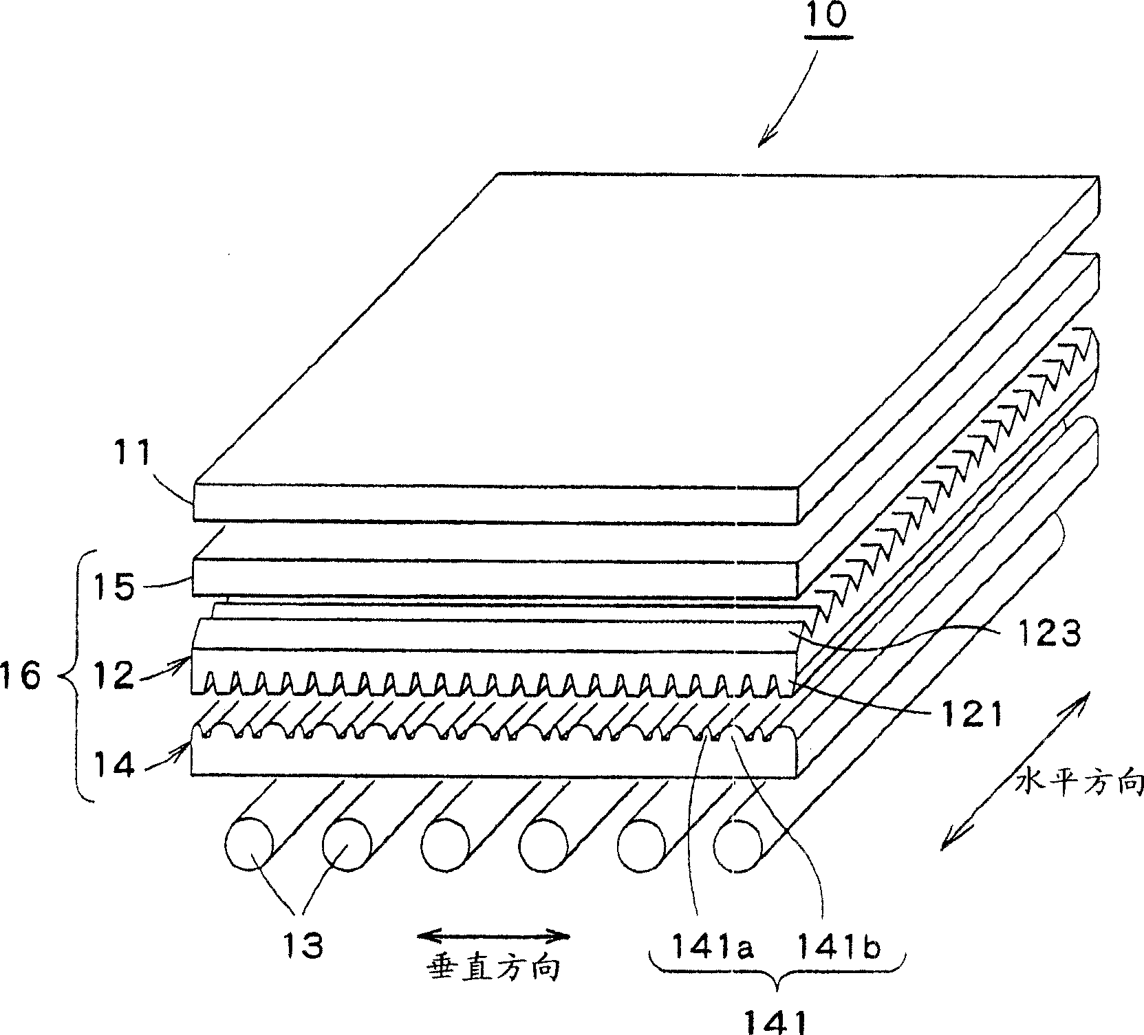
Embodiments of the present invention will be described below with reference to the drawings.

Such as figure 1 As shown, the transmissive display device 10 of an embodiment of the present invention is a transmissive liquid crystal display device that displays image information by controlling the transmission / non-transmission of light with a liquid crystal display element, wherein it is provided with: LCD screen (transmissive display Part) 11 and a light source device 16 for illuminating the LCD screen 11 from the back. Wherein, the surface light source device 16 is at least provided with a converging plate 12, a cathode ray tube 13, a diffuser plate 14 and a reflective polarizer 15, and the surface light source device 16 is used to view the LCD screen 11 corresponding to the image pattern of the image information from the back side. By irradiating light, an image can be displayed on the LCD panel 11 . Furthermore, including figure 1 The following figures including ...


PUM

PropertyMeasurementUnit
refractionaaaaaaaaaa

Abstract

A diffusion sheet capable of unevenness-free, uniform lighting regardless of a screen observing position, a surface light source device and a transmitting display unit. The transmitting display unit (10) comprises an LCD panel (11) and a surface light source device (16) for illuminating the LCD panel (11) from behind. The surface light source device (16) has a plurality of cathode ray tubes (13) arranged side by side. A diffusion sheet (14) and a converging sheet (12) are provided between the cathode ray tubes (13) of the surface light source device (16) and the LCD panel (11). Diffusion lens arrays (141) are formed on the light outgoing side of the diffusion sheet (14). The diffusion lens arrays (141) have a plurality of unit lens (a plurality of sets each consisting of a low unit lens (141a) and a high unit lens (141b) that are arranged are regularly arranged and disposed) each of which forming a shape corresponding to part of an elliptical tube having an elliptical section. The converging sheet (12) has a plurality of unit lenses (121) that are formed along the sheet surface on the cathode ray tube (13) side and have almost trapezoidal sectional shapes. The above arrangement can diffuse lighting lights from the cathode ray tubes (13) of the surface light source device (16) to provide a uniform lighting and converge lighting lights to enhance a light utilization efficiency as a back light.

Description

technical field [0001] The present invention relates to a display device such as a liquid crystal display device, and more particularly to a diffuser plate used for a surface light source device such as a transmissive liquid crystal display device backlighting, a surface light source device, and a transmissive display device using them. Background technique [0002] As a surface light source device for illuminating a transmissive liquid crystal display device or the like from the back, various types of surface light source devices have been proposed and put into practical use. Such surface light source devices are mainly classified into edge light type and direct type according to the method of converting a non-surface light source into a surface light source. [0003] Among them, for example, a direct-type surface light source device is configured by using cathode ray tubes (light-emitting tubes) arranged in parallel to directly introduce light from the back of a tran...

Claims


Application Information

Patent Timeline
Patent Type & Authority Patents(China)
IPC IPC(8): G02B5/02F21S2/00F21V5/04G02B3/00G02F1/1335G02F1/13357
Inventor 后藤正浩
Owner DAI NIPPON PRINTING CO LTD
Why Eureka
Try Eureka