Touch control type planar display and producing method thereof

A flat-panel display and manufacturing method technology, applied to static indicators, instruments, electrical digital data processing, etc., can solve the problems of inability to achieve thinness, increase the cost of zero components, increase the overall thickness and weight of the display, and achieve improved wear. Effects of transmittance and cost reduction

Active Publication Date: 2009-04-08
AU OPTRONICS CORP
View PDF8 Cites 0 Cited by
  • Summary
  • Abstract
  • Description
  • Claims
  • Application Information

AI Technical Summary

Problems solved by technology

[0004] However, in such a device with a touch panel disposed on the surface of a general display panel, the overall thickness and weight of the display will be increased, and the requirement for thinning cannot be achieved.
In addition, the addition of a touch panel will reduce the transmittance of the backlight of the LCD display, resulting in a decrease in brightness
Furthermore, adding the touch panel on the display panel will also increase the cost of components

Method used


Image

  • Touch control type planar display and producing method thereof
  • Touch control type planar display and producing method thereof
  • Touch control type planar display and producing method thereof

Examples


Embodiment 1

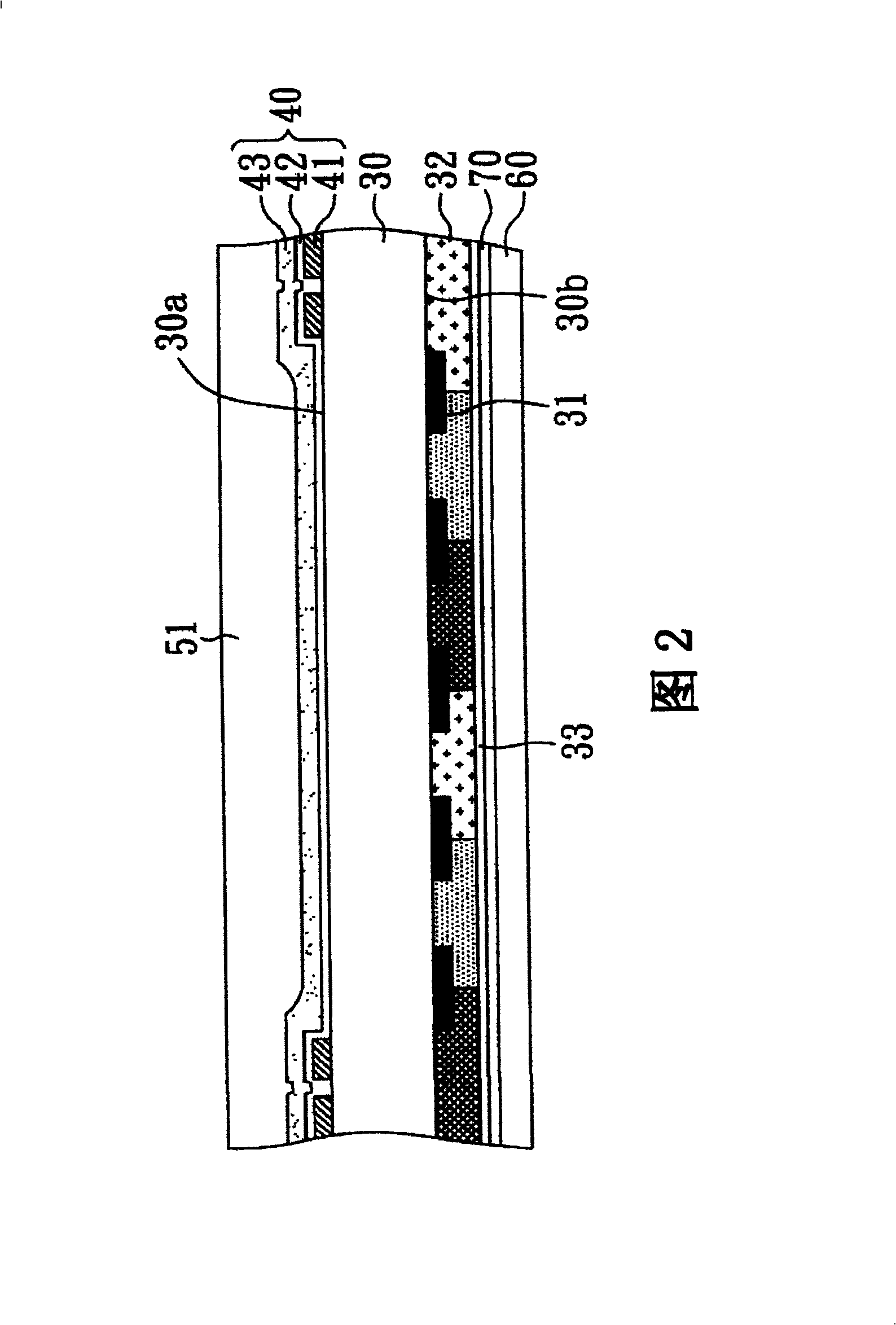
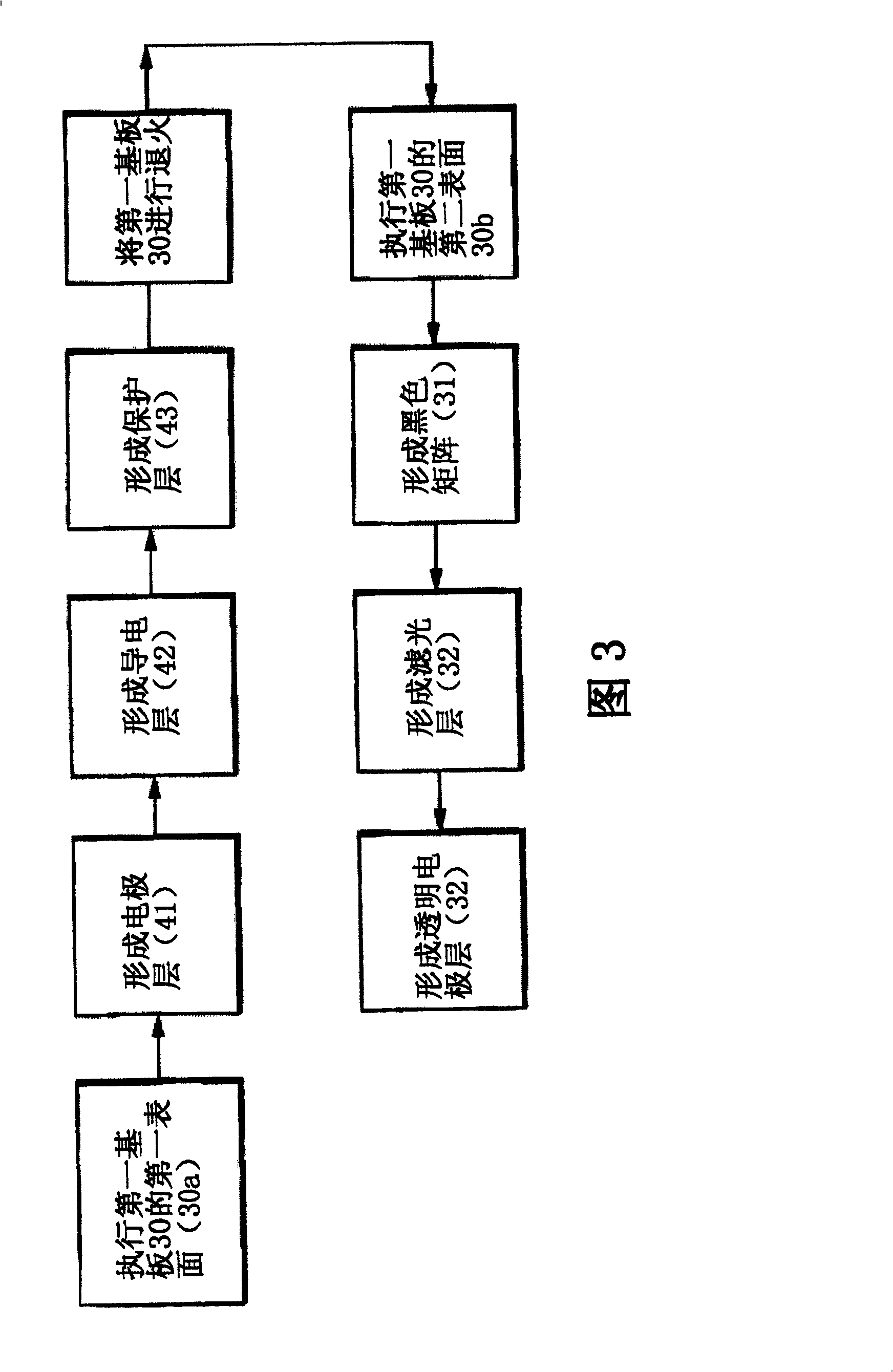
[0055] Please refer to FIG. 2 and FIG. 3 at the same time, wherein FIG. 2 is a cross-sectional view of the touch-sensitive flat panel display of the present invention, and FIG. 3 is a flow chart of the present invention for manufacturing the first substrate. The steps of manufacturing the touch-sensitive flat panel display of this embodiment include: firstly, providing a first substrate 30 having a first surface 30a and a second surface 30b. Here, the material used for the first substrate 30 may be a glass substrate.

[0056] Next, a touch unit 40 is formed on the first surface 30 a of the first substrate 30 , and the step of forming the touch unit 40 is: first forming a patterned electrode layer 41 on the first surface 30 a of the first substrate 30 , wherein , the material used for this electrode layer 41 can be Mo / Al (form aluminum (Al) first, then form molybdenum (Mo)) or can be Mo / Al / Mo (form Mo first, then form Al, and then form Mo) . And, the patterned electrode layer...

Embodiment 2

[0061] This embodiment is substantially the same as Embodiment 1, but the difference is that, please refer to FIG. Use polarizing materials or directly attach polarizers, and can polarize light. Therefore, the protective layer 431 in this embodiment also has the function of the polarizer 51 (as shown in FIG. 2 ) in the first embodiment. Therefore, in this embodiment, the step of additionally attaching the polarizer 51 (as shown in FIG. 2 ) is not performed. All the other steps and structures are the same as in Example 1.

Embodiment 3

[0063] This embodiment is substantially the same as Embodiment 1, but the difference is that please refer to FIG. 7 and FIG. 8 . In this embodiment, when manufacturing the touch unit 40 , a conductive layer 42 is first formed on the first surface of the first substrate 30 30a on. Then, a patterned electrode layer 41 is formed on the surface of the conductive layer 42, wherein the material used for the electrode layer 41 can be Al / Mo (form Mo first, then Al) or Mo / Al / Mo (form first Mo is formed, then Al is formed, and Mo is formed again). The patterned electrode layer 41 is correspondingly formed on the periphery of the first substrate 30 , and its pattern can be the same as that shown in the first embodiment. All the other steps are the same as in Example 1.


PUM


Abstract

This invention relates to a sort of touch-control type plane display and its manufacturing method. This touch-control type plane display consists of the first base plate, the second base plate, the touch-control unit and the liquid crystal layer. The first base plate has a first surface and a second surface. The second base plate has the element array which corresponds to the second surface of the first base plate. The touch-control unit is fixed in the first surface of the first base plate and it consists of the conducting layer, the electrode layer and the protecting layer which have the pattern. The electrode layer is fixed in the edge of the first base plate, and the protecting layer covers the conducting layer and the electrode which has the pattern, and the conducting layer is fixed between the protecting layer and the first base plate. The liquid crystal layer is fixed between the first base plate and the second base plate.

Description

technical field [0001] The invention relates to a touch-sensitive flat panel display, in particular to a thinned touch-sensitive flat-panel display. Background technique [0002] In general, touch panel devices are often used as input devices for personal computers, notebook computers, personal digital assistants (PDAs) or the like, where information can be entered on the display screen of the display device with a finger or a pen. is input by touching it. [0003] The current touch display is to install a touch panel on the surface of the general display panel. The touch panel has many different touch technologies, such as capacitive, resistive, acoustic and infrared (optical). ) and other four. Take the capacitive touch panel commonly used in public places as an example. Please refer to FIG. 1 , which is a cross-sectional view of a touch display device in the prior art. The touch display device includes: a display panel 10 and a touch panel 20 . The display panel 10 s...

Claims


Application Information

Patent Timeline
Patent Type & Authority Patents(China)
IPC IPC(8): G02F1/133G06F3/041
Inventor 刘柏源赖明升刘俊欣蔡昆华
Owner AU OPTRONICS CORP
Why Eureka
Try Eureka