Centrifugal fan and heat dissipation system

A centrifugal fan and fan technology, which is applied in the fields of instruments, electrical digital data processing, digital data processing components, etc., can solve problems such as hindering and affecting the development of thinning of electronic devices, and difficulty in reducing the thickness of centrifugal fans.

Active Publication Date: 2020-05-26
SHENXUN COMP KUNSHAN +1
View PDF9 Cites 0 Cited by
  • Summary
  • Abstract
  • Description
  • Claims
  • Application Information

AI Technical Summary

Problems solved by technology

Therefore, in the prior art, in order to maintain a certain heat dissipation effect, it is difficult to reduce the thickness of the centrifugal fan, which hinders the development of thinning electronic devices.

Method used


Image

  • Centrifugal fan and heat dissipation system
  • Centrifugal fan and heat dissipation system
  • Centrifugal fan and heat dissipation system

Examples


Embodiment Construction

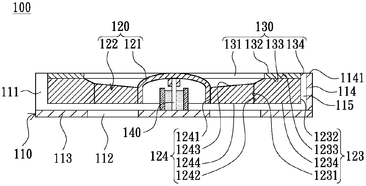
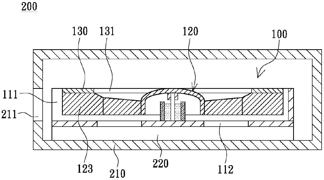
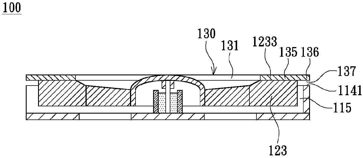
[0016] figure 1 It is a schematic cross-sectional view of a centrifugal fan according to an embodiment of the present invention. Please refer to figure 1 , the centrifugal fan 100 of this embodiment includes a fan base 110 , an impeller 120 and a fan cover 130 . The fan base 110 has an air outlet 111 and a first air inlet 112 . The impeller 120 is rotatably disposed on the fan base 110 , and the impeller 120 includes a central portion 121 and a plurality of fan blades 122 . The central portion 121 is pivotally connected to the fan base 110 . Each blade 122 has a first blade portion 123 and a second blade portion 124 . The second blade portion 124 is connected between the first blade portion 123 and the central portion 121 . The fan cover 130 is opposite to the fan base 110 , and the fan cover 130 is disposed on a side of the first blade portion 123 of the fan blade 122 away from the fan base 110 . The fan cover 130 has a second air inlet 131 . The first air inlet 112 and...


PUM


Abstract

The invention relates to a centrifugal fan and a heat dissipation system. The centrifugal fan comprises a fan base, an impeller and a fan cover, wherein the fan base is provided with an air outlet anda first air inlet; the impeller is rotatably arranged on the fan base and comprises a central part and fan blades, the central part is pivoted with the fan base, each fan blade is provided with a first fan blade part and a second fan blade part, and the second fan blade part is connected between the first fan blade part and the central part; the fan cover is opposite to the fan base, arranged onthe side face, away from the fan base, of the first fan blade part and provided with a second air inlet; the first air inlet and the second air inlet are located in the two opposite sides of the second fan blade parts respectively; the heat dissipation system comprises a shell, a heat source and the centrifugal fan; the centrifugal fan is arranged in the shell and is adjacent to the heat source; and heat energy generated by the heat source reaches a ventilation opening of the shell through the first air inlet, the impeller and the air outlet so as to leave from the shell. By means of the centrifugal fan and the heat dissipation system, an electronic device can have the advantages of being thin and capable of effectively dissipating heat.

Description

【Technical field】 [0001] The invention relates to a centrifugal fan and a cooling system. 【Background technique】 [0002] The centrifugal fan in the prior art is often used in electronic devices such as notebook computers for heat dissipation due to its flat structure. However, based on the market demand, the electronic devices in the prior art are constantly developing towards thinning. However, one of the technical bottlenecks in the thinning of electronic devices in the prior art is the centrifugal fan. The centrifugal fan in the prior art has reached the thickness limit of effective heat dissipation; when the casing thickness of the centrifugal fan is reduced, the air volume of the centrifugal fan is also reduced accordingly; Play the role of effective heat dissipation. Therefore, in the prior art, it is difficult to reduce the thickness of the centrifugal fan in order to maintain a certain heat dissipation effect, which hinders the development of thinning electronic ...

Claims


Application Information

Patent Timeline
IPC IPC(8): F04D25/08F04D29/42F04D29/28F04D29/30G06F1/20
CPCF04D25/08F04D29/281F04D29/30F04D29/4226G06F1/203
Inventor 萧惟中
Owner SHENXUN COMP KUNSHAN
Why Eureka
Try Eureka