Supercharge Your Innovation With Domain-Expert AI Agents!

Electric power bias circuit with negative feedback

A power supply bias circuit, negative feedback technology, applied in the direction of adjusting electrical variables, instruments, control/regulating systems, etc., can solve the problems of the power supply rejection ratio cannot reach the accuracy, the overall structure is not cost-effective, and there is no feedback circuit. The effect of good bias current, reduced sensitivity and high precision

Inactive Publication Date: 2009-04-08
HUAZHONG UNIV OF SCI & TECH
View PDF6 Cites 0 Cited by
  • Summary
  • Abstract
  • Description
  • Claims
  • Application Information

AI Technical Summary

Problems solved by technology

[0004] In the classic book "Analog CMOS Integrated Circuit Design" published by Xi'an Jiaotong University Press and translated by Chen Guican and others, page 311 describes a power bias circuit, but it does not have any feedback circuit , so its power supply rejection ratio cannot achieve a higher accuracy, making it still unable to meet the requirements in high-precision applications
Moreover, it requires an additional startup circuit, and the cost performance of the overall structure is not high

Method used


Image

  • Electric power bias circuit with negative feedback
  • Electric power bias circuit with negative feedback
  • Electric power bias circuit with negative feedback

Examples


Embodiment Construction

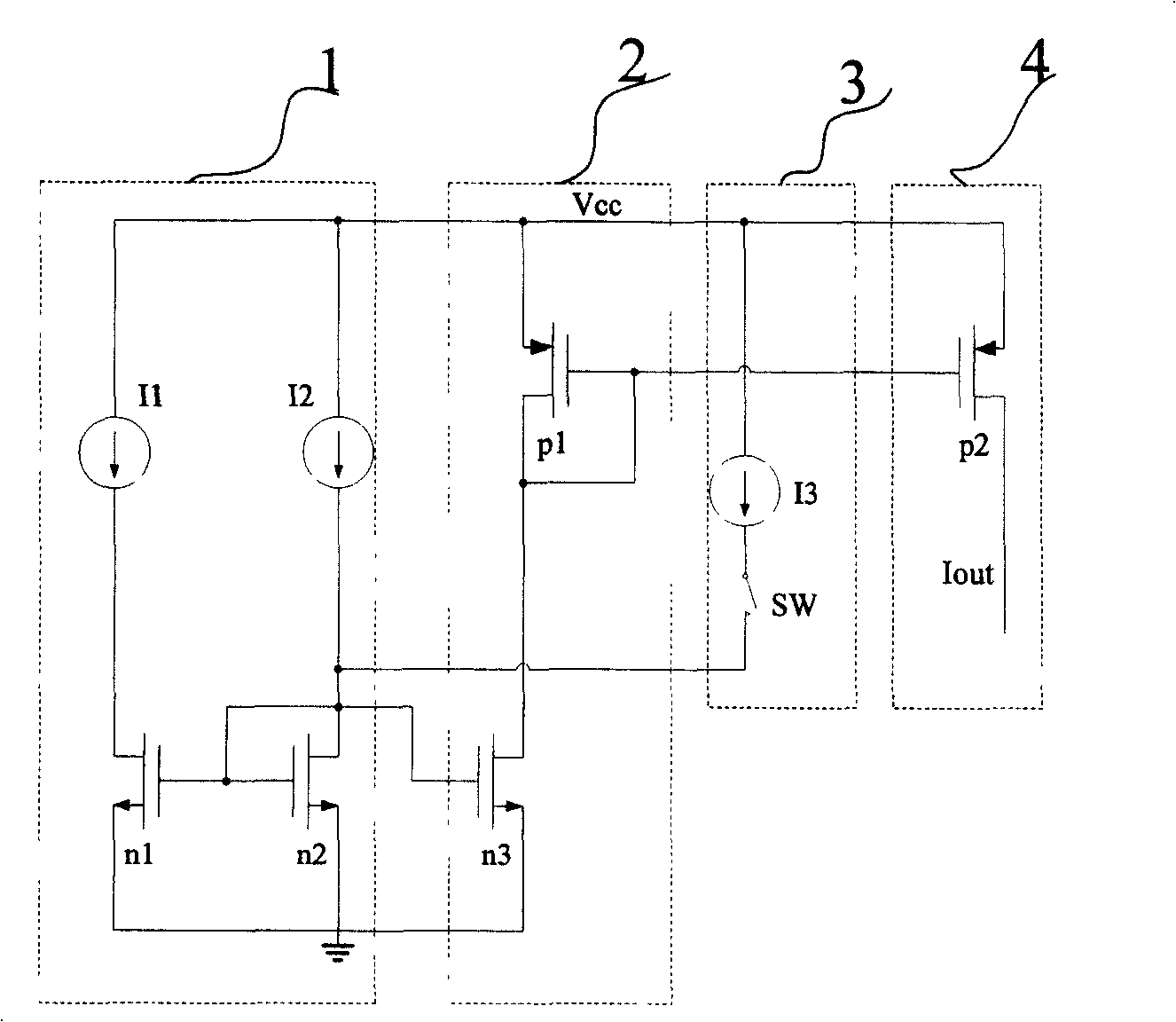
[0013] like figure 1 As shown, the power supply bias circuit with negative feedback of the present invention includes a bias generation circuit 1, a mirror image branch 2, a feedback branch 3 and a current output branch 4, and the working principle of the circuit is described below.

[0014] The mirror currents generated by current sources I1 and I2 flow through NMOS transistor n1 and NMOS transistor n2 respectively. When the currents in NMOS transistor n1 and NMOS transistor n2 are equal, the SW is turned off, and the mirror current passes through PMOS transistor p1, and NMOS transistor n3 is mirrored to PMOS transistor p2 outputs; when I1 and I2 are not equal, the switch SW is turned on, I3 flows into the NMOS transistor n2, and the current flowing through the NMOS transistor n2 is compensated so that the current flowing through the NMOS transistor n1 is equal to the current flowing through the NMOS transistor n2. The compensated current in the NMOS transistor n2 is mirrored...


PUM


Abstract

The invention relates to electrical source biasing circuit with negative feedback. It includes biasing generating circuit, mirror image branch circuit, feedback branch circuit, current output branch circuit. The biasing generating circuit is formed by electrical source I1, I2, NOMS tube n1, n2, used to generate bias current. The mirror image branch circuit is formed by PMOS tube p1 and NMOS tube n3, used to image the current to output branch circuit. The feedback branch circuit is formed by electrical source I3, equivalent switch, used to generate current feedback quantity, adjust bias current. The current output branch circuit is formed by PMOS tube p5, used to output stable bias current. The invention fixes the indifferent bias on the fixed value, can stabilize output bias current, and reduce source voltage sensitivity better compared with the existing current bias circuit. It inducts negative feedback, makes output bias current have higher precision by adjusting current in bias generating circuit.

Description

technical field [0001] The invention belongs to the field of analog integrated circuits, and in particular relates to a power supply bias circuit with negative feedback, which can effectively provide a bias current irrelevant to the power supply. Background technique [0002] With the development of society, people have higher and higher requirements on the performance of consumer electronic products. This puts higher and higher performance requirements on corresponding consumer ICs. The function of the bias circuit is mainly to provide suitable bias current for other working modules to determine the quiescent operating point of the amplifier. A high-quality bias circuit is usually required inside an integrated circuit to provide a stable bias current. For multi-channel integrated op amps, due to the basic use of a common bias circuit, it is even necessary to consider the mutual crosstalk between adjacent channels. [0003] The existing power-independent bias circuit usua...

Claims


Application Information

Patent Timeline
Patent Type & Authority Patents(China)
IPC IPC(8): G05F1/46G05F1/56
Inventor 邹雪城鲁力刘政林张程龙宁军余凯
Owner HUAZHONG UNIV OF SCI & TECH
Features
  • R&D
  • Intellectual Property
  • Life Sciences
  • Materials
  • Tech Scout
  • Unparalleled Data Quality
  • Higher Quality Content
  • 60% Fewer Hallucinations
Learn More