Frother mixing head

A technology of mixing head and foaming machine, applied in the direction of liquid injection device, injection device, etc., can solve the problems of bulky volume, clogging of the feeding port, high density, etc., to simplify the mechanical transmission structure, improve product quality, and improve transmission efficiency. Effect

Inactive Publication Date: 2009-05-06
JIMEI UNIV
View PDF8 Cites 0 Cited by
  • Summary
  • Abstract
  • Description
  • Claims
  • Application Information

AI Technical Summary

Problems solved by technology

At present, many manufacturers have changed the main parts of the original polyurethane continuous foaming equipment to anti-corrosion materials for the production of phenolic foam materials. Due to the high viscosity and high density of phenolic resin, it often occurs In fact, normal continuous production cannot be realized due to problems such as blockage of the feed port, backflow of resin raw materials and mixtures to other material pipelines, etc.
In addition, the higher the impeller speed of the mixing head, the better the product quality. The existing equipment often adopts belt or gear speed increase, which has problems such as bulky size and low efficiency, and the maximum speed that can be achieved is very limited.

Method used


Image

  • Frother mixing head
  • Frother mixing head

Examples


Embodiment 1

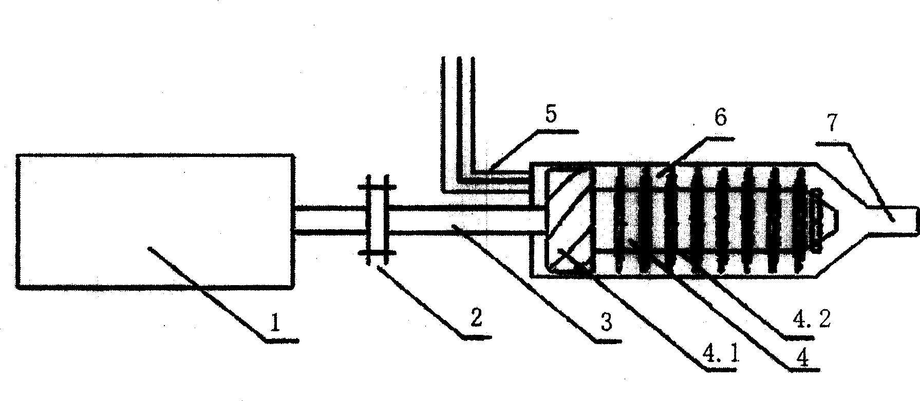
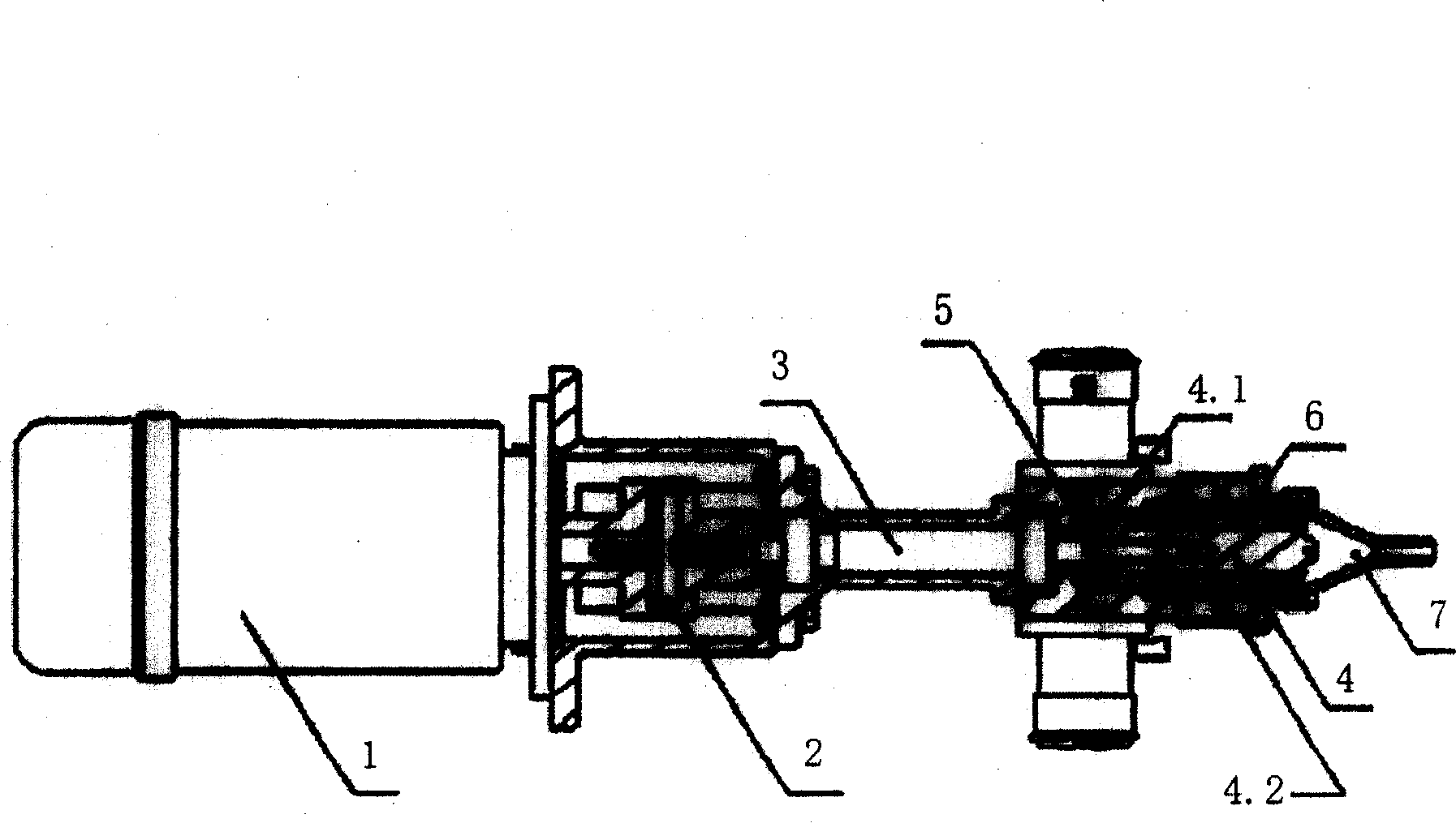
[0012] Such as figure 1 , shown in 2, the present invention is provided with motor 1, shaft coupling 2, impeller shaft 3, impeller 4, 3 axial feed pipes 5, material mixing chamber 6 and nozzle 7, impeller shaft 3 is connected with shaft coupling 2 The motor 1 is connected, the impeller 4 is placed in the material mixing chamber 6, the axial feeding pipe 5 is connected with the material mixing chamber 6 through the axial feeding port, and the front end of the material mixing chamber 6 is connected with the mixing nozzle 7. The impeller 4 is divided into two functional sections: a helical propelling section 4.1 and a blade mixing section 4.2.

Embodiment 2

[0014] Similar to Embodiment 1, the difference is that a radial feed pipe can be provided, and the radial feed pipe is connected to the material mixing chamber through a radial feed port.

[0015] A motor with a speed of 3600 r / min or more can be used, and the structure directly connected with the impeller shaft is adopted without passing through the speed increasing mechanism.

[0016] see figure 1 , 2, A variety of liquid materials enter the mixing chamber 6 from the three axial feed pipes 5 through the axial feed port. Due to the high-speed rotation of the impeller screw propulsion section 4.1, the negative pressure near the feed inlet is caused, so that the material enters the mixing chamber smoothly. If the viscosity and density of the main material are particularly high, the radial feeding pipe located in the mixing section can directly enter the mixing chamber through the radial feeding port, while the low-density material still enters the mixing chamber through the ax...


PUM


Abstract

A mixing head of foaming machine for continuous foaming of high-viscosity resin, multi-component fluid and plastics is composed of electric motor, blade wheel, material mixing cavity with nozzle at its front end, and at least one material feeding pipe. Its advantages are simplified drive mechanism, high rotation speed, and high quality of product.

Description

technical field [0001] The invention relates to a plastic pressure foam molding equipment, which is mainly used for the continuous foaming production of various resin foams, especially for the continuous foaming of high-viscosity resins such as phenolic resins and other multi-component products that require high-speed stirring. Foaming machine mixing head for fluid mixing and foaming production. Background technique [0002] Phenolic foam material is a new type of flame-retardant foam insulation material. Due to the difference in raw material viscosity, its production equipment is very different from the current mature polyurethane foam equipment. At present, many manufacturers have changed the main parts of the original polyurethane continuous foaming equipment to anti-corrosion materials for the production of phenolic foam materials. Due to the high viscosity and high density of phenolic resin, it often occurs Problems such as blockage of the feed port, backflow of resin ...

Claims


Application Information

Patent Timeline
Patent Type & Authority Patents(China)
IPC IPC(8): B29C67/20B05B7/04
Inventor 陈扼西冯培锋
Owner JIMEI UNIV
Why Eureka
Try Eureka