

Two-for-one twister multi-motor intelligent control system
An intelligent control system and double twisting machine technology, applied in spinning machines, continuous winding spinning machines, textiles and papermaking, etc., can solve the problems of complex transmission structure, easy damage of internal parts, affecting the operation effect, etc. Simplified mechanical transmission structure, good running effect and convenient production
- Summary
- Abstract
- Description
- Claims
- Application Information
AI Technical Summary
Problems solved by technology
Method used
Image

Examples
Embodiment Construction
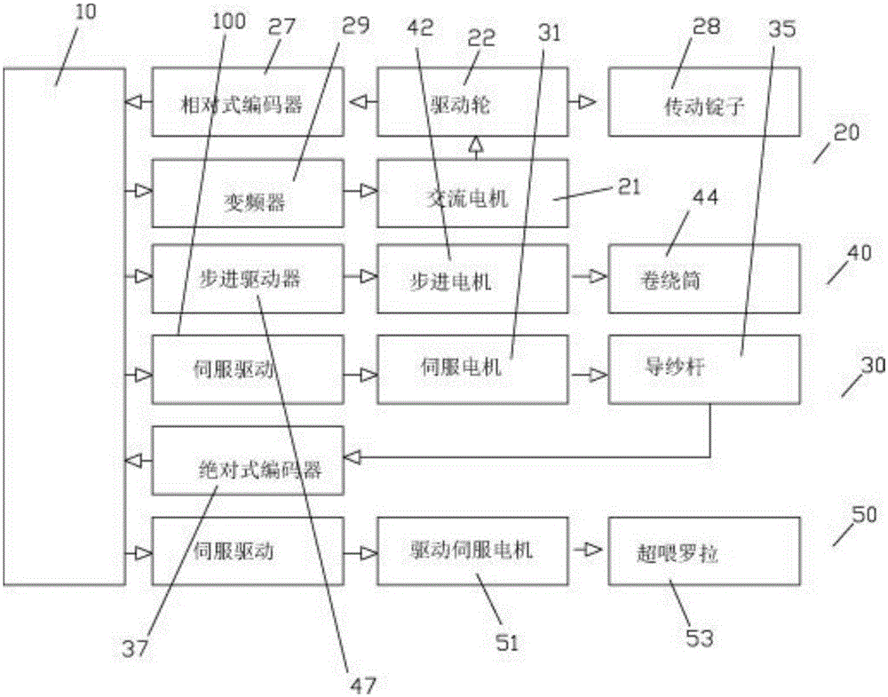
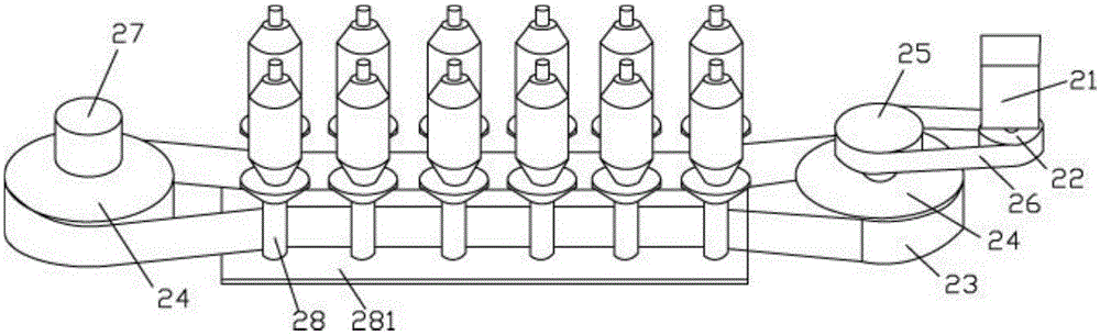
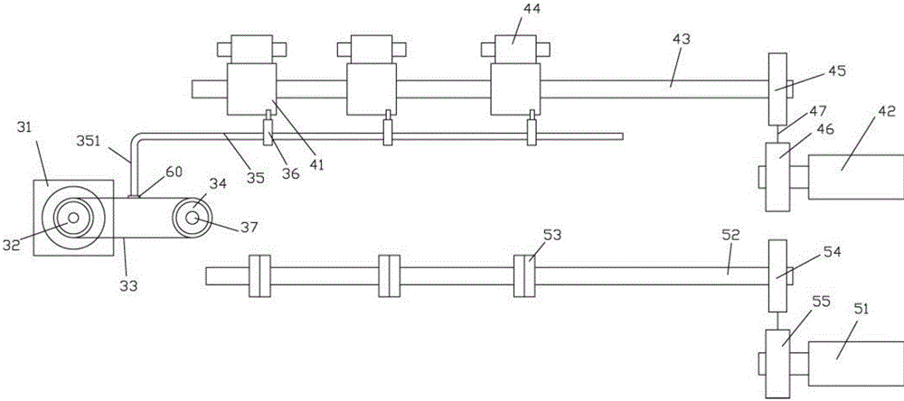
[0025] Examples, see e.g. Figures 1 to 6 As shown, a two-for-one twister multi-motor intelligent control system includes a two-for-one twister control host 10, a dragon belt spindle transmission mechanism 20, a yarn take-up transmission mechanism 40, a yarn guide rod and a yarn guide transmission mechanism 30, and an overfeed transmission mechanism 50, the two-for-one twister control host 10 controls the operation of the AC motor 21 of the dragon belt spindle transmission mechanism 20, the output shaft of the AC motor 21 is fixed with a drive wheel 22, and the dragon belt 23 is tensioned on two synchronous pulleys 24, The connecting shaft of one of the synchronous pulleys 24 is fixed with a transmission pulley 25, and the belt 26 is tensioned on the driving pulley 22 and the transmission pulley 25. On the connecting shaft of the other synchronous pulley 24, a relative encoder 27 is fixed. The encoder 27 is connected to the main board of the two-for-one twister control host 10...
PUM
 Abstract
Description
Claims
Application Information