
Method and base chip for monitoring the operation of a microcontroller unit

A technology of microcontrollers and substrates, applied in general control systems, hardware monitoring, program control, etc., can solve problems such as helplessness

Inactive Publication Date: 2009-05-06
NXP BV
View PDF5 Cites 0 Cited by
  • Summary
  • Abstract
  • Description
  • Claims
  • Application Information

AI Technical Summary

Problems solved by technology

[0006] Even the so-called "watchdog timers" that existing SoCs have are unhelpful in this regard

Method used


Image

  • Method and base chip for monitoring the operation of a microcontroller unit
  • Method and base chip for monitoring the operation of a microcontroller unit

Examples


Embodiment Construction

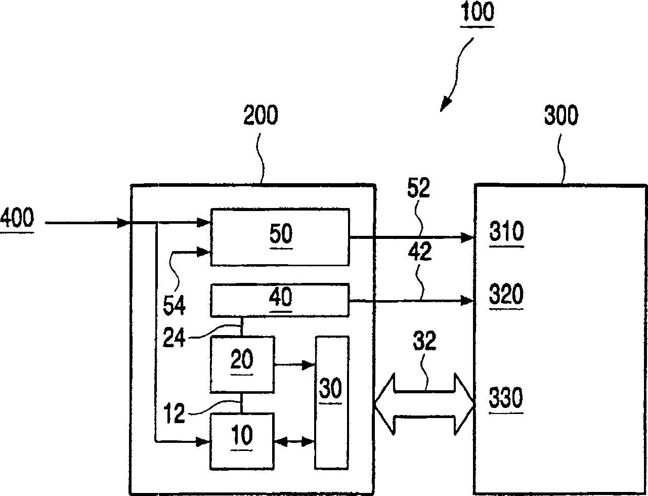
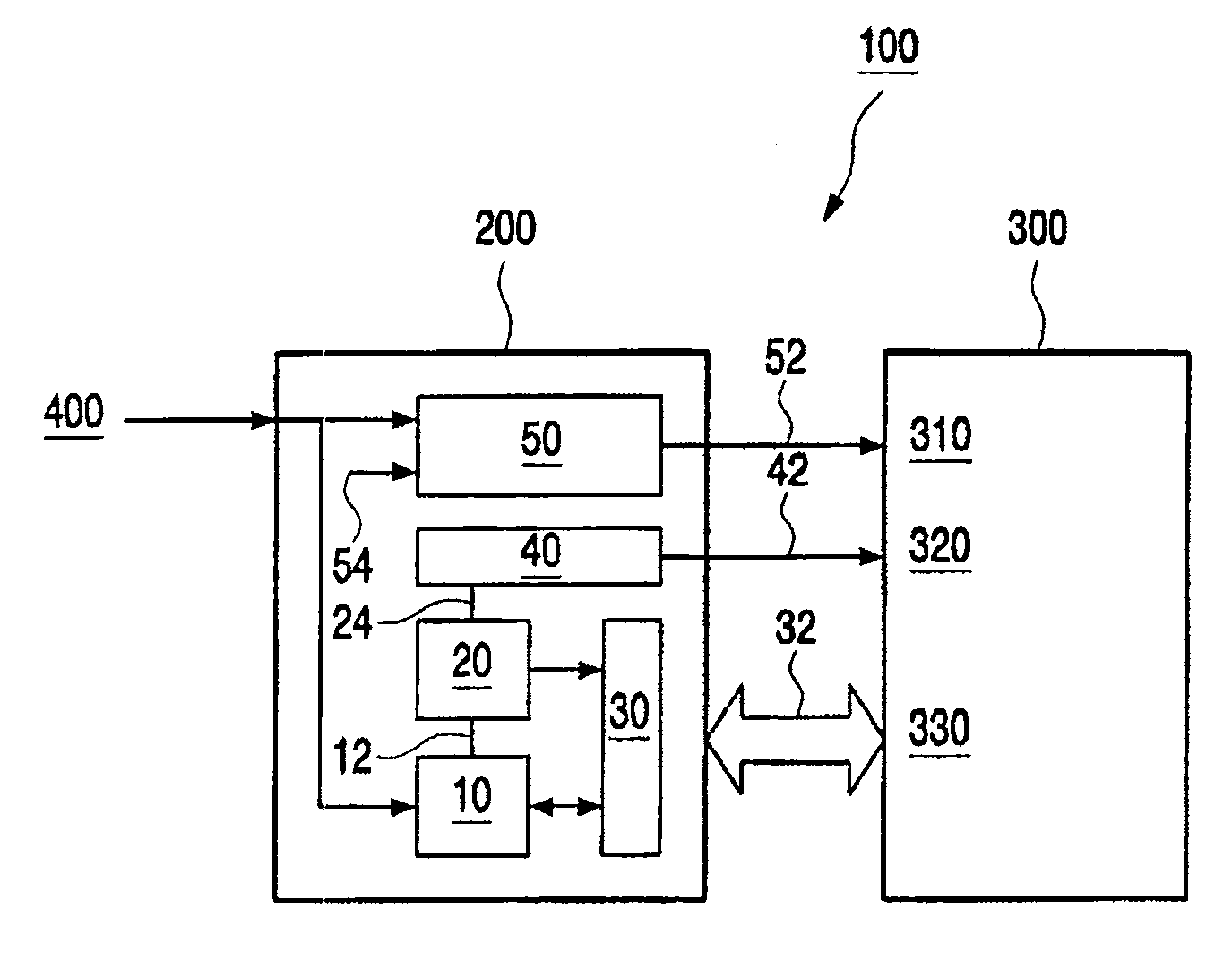
[0020] exist figure 1 A control system 100 is schematically shown in , and a microcontroller unit 300 with a power supply unit 310 (providing VDD power), a reset unit 320 and an I / O (input / output) module 330, also having a so-called SBC ( system substrate) 200 for monitoring the operation of the microcontroller unit 300 acting on the application.

[0021] For this purpose, said SoC 200 has in particular a supervisory module (=watchdog timer unit) 10, by means of a confirmation signal the fact that a reset of the microcontroller unit 300 has taken place can be confirmed, thus being able to implement a so-called "reset signal Exchange" function. In other words, this means that the watchdog timer unit 10 receives confirmation from the application of a reset event that the watchdog timer unit 10 has issued a reset command; in this way, figure 1 The monitoring module 10 shown in , makes it possible to detect and record an interrupt reset line 42 .

[0022] In this regard, the ...


PUM


Abstract

In order to further develop a method and a substrate (200) for monitoring the operation of at least one microcontroller acting on at least one application and associated with the system (100) by reliably detecting faults in, and forming conclusions that need to be formed for system-related causes, it is suggested that: said microcontroller unit (300) has at least one monitoring module (10) associated therewith; (10) Confirm the fact that the reset of the microcontroller unit (300) has occurred.

Description

[0001] field of invention [0002] The invention relates to a method of monitoring the operation of at least one microcontroller unit acting on at least one application and associated with a system. [0003] The invention also relates to a substrate, and in particular to a system substrate, for monitoring the operation of at least one microcontroller unit acting on at least one application, and to a related A connected system, in particular to a control system. Background technique [0004] One of the most important hardware signals in a control unit is the reset signal, whose purpose is to reset the application hardware if a system failure occurs. In certain applications, provision is made intentionally by the user for resetting the hardware, for example to enable a partial program to start in a programmed, ordered state in a microcontroller with software. [0005] However, as far as the prescribed reset is concerned, in existing applications there is no feedback whether a...

Claims


Application Information

Patent Timeline
IPC IPC(8): G06F11/00G06F1/24G06F11/30G05B9/02G05B19/048
CPCG06F1/24
Inventor M·瓦纳M·穆特
Owner NXP BV
Learn More