Supercharge Your Innovation With Domain-Expert AI Agents!

Plasma display driving device and driving method

A plasma display and scanning electrode technology, applied in identification devices, static indicators, instruments, etc., can solve the problems of increasing PDP costs, and achieve the effect of reducing manufacturing costs and stabilizing driving

Inactive Publication Date: 2009-05-06
LG ELECTRONICS(NANJING) PLASMA CO LTD
View PDF4 Cites 0 Cited by
  • Summary
  • Abstract
  • Description
  • Claims
  • Application Information

AI Technical Summary

Problems solved by technology

Therefore, a plurality of DC-DC conversion circuits providing different voltage values ​​are required on the PDP driving device of the prior art, which brings about the problem of increasing the cost of the PDP.

Method used


Image

  • Plasma display driving device and driving method
  • Plasma display driving device and driving method
  • Plasma display driving device and driving method

Examples


Embodiment Construction

[0047] A practical example of the present invention will be further described below.

[0048] The following will be by reference Figure 4 to Figure 15 , to describe practical examples of the present invention.

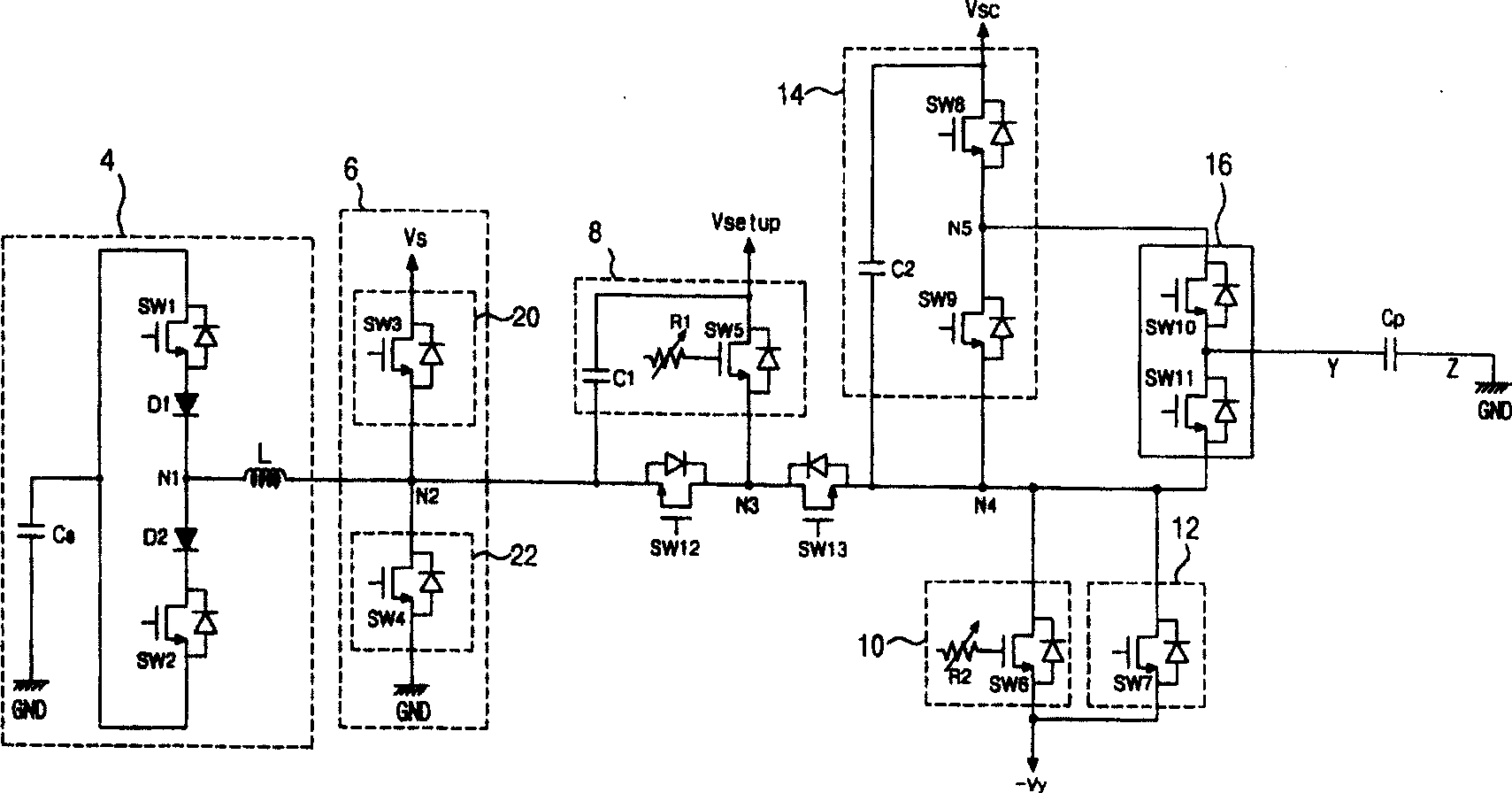
[0049] Figure 4 It is a schematic example of a plasma display driving device when the present invention is adopted.

[0050] Such as Figure 4 As shown, the driving device adopting the plasma display of the present invention includes an energy recovery / supply circuit 54; a sustain pulse supply circuit 56; a SET UP voltage supply control circuit 58; a SET DOWN voltage supply control circuit 60; a scanning voltage supply control circuit 62; A reference voltage supply control circuit 64; a scanning integrated circuit (Intergrated Circuit; hereinafter referred to as "IC") 66; a scanning voltage source 68; a switch 12 (SW12) and a switch 13 (SW13). The driving device of this kind of plasma display (Plasma Display Panel; hereinafter referred to as "PDP") provides drivi...


PUM


Abstract

The invention discloses a driving device and driving method of plasma display. It includes scan electrodes maintaining pulse supply circuits which provides to panel capacitance maintaining pulse with maintaining voltage and ground voltage; scan voltage source which generates negative maintaining voltage, and is connected with the mentioned maintaining pulse supply circuits and scan electrodes. The driving method is divided into initialization time, addressing time and maintaining time. In the descendent period of initialization time, the voltage is provided to scan electrodes of plasma displays as descendent wave forms; in the addressing time, the scan pulse with negative maintaining voltage is provided to scan electrodes. The invention can reduce the number of needed powers to drive plasma display.

Description

1. Technical field [0001] The invention relates to a plasma display, in particular to a plasma display driving device and a driving method for reducing cost by reducing the number of power sources required for driving the plasma display. 2. Background technology [0002] A plasma display (Plasma Display Panel; hereinafter referred to as "PDP") uses ultraviolet rays generated during discharge of inert mixed gases such as He+Xe, Ne+Xe, He+Xe+Ne, etc., and the ultraviolet rays excite phosphors to make the phosphors emit light and display images. This type of PDP is not only easy to thin and large, but also injects new power into the recent technological development and greatly improves the picture quality. [0003] figure 1 A pattern diagram of the 8-bit default code (c) subfield for displaying 256 gray levels for a plasma display. [0004] Such as figure 1 As shown, the PDP is used to display the tone of the picture, and divides a frame of image into different sub-fields to...

Claims


Application Information

Patent Timeline
IPC IPC(8): G09G3/20G09G3/28G09F9/313H01J17/49G09G3/288
Inventor 朴現一文聖學
Owner LG ELECTRONICS(NANJING) PLASMA CO LTD
Features
  • R&D
  • Intellectual Property
  • Life Sciences
  • Materials
  • Tech Scout
  • Unparalleled Data Quality
  • Higher Quality Content
  • 60% Fewer Hallucinations
Learn More