Bent axle push-stopping surface polishing device

A technology of polishing device and thrust surface, applied in grinding/polishing equipment, grinding machines, metal processing equipment, etc., can solve the problems of complex structure, low work efficiency, high price, etc., achieve high processing finish, reduce labor intensity, and produce high efficiency effect

Inactive Publication Date: 2009-05-13
TIANRUN IND TECH CO LTD
View PDF4 Cites 0 Cited by
  • Summary
  • Abstract
  • Description
  • Claims
  • Application Information

AI Technical Summary

Problems solved by technology

The existing crankshaft thrust surface polishing device generally adopts a special crankshaft thrust surface polishing machine, which has complex structure, high price, low work efficiency and inconvenient use
Among them, the winding mechanism is driven by gear shifting, and the structure is more complicated.
The whole machine must be integrated when used, and it cannot be installed and used at will.

Method used


Image

  • Bent axle push-stopping surface polishing device
  • Bent axle push-stopping surface polishing device
  • Bent axle push-stopping surface polishing device

Examples


Embodiment Construction

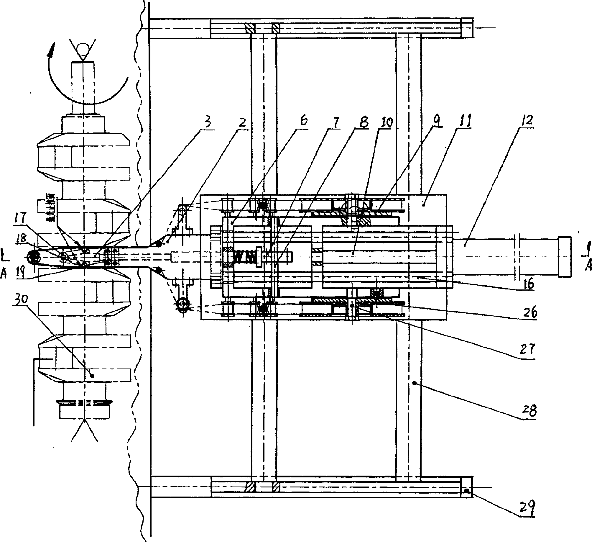
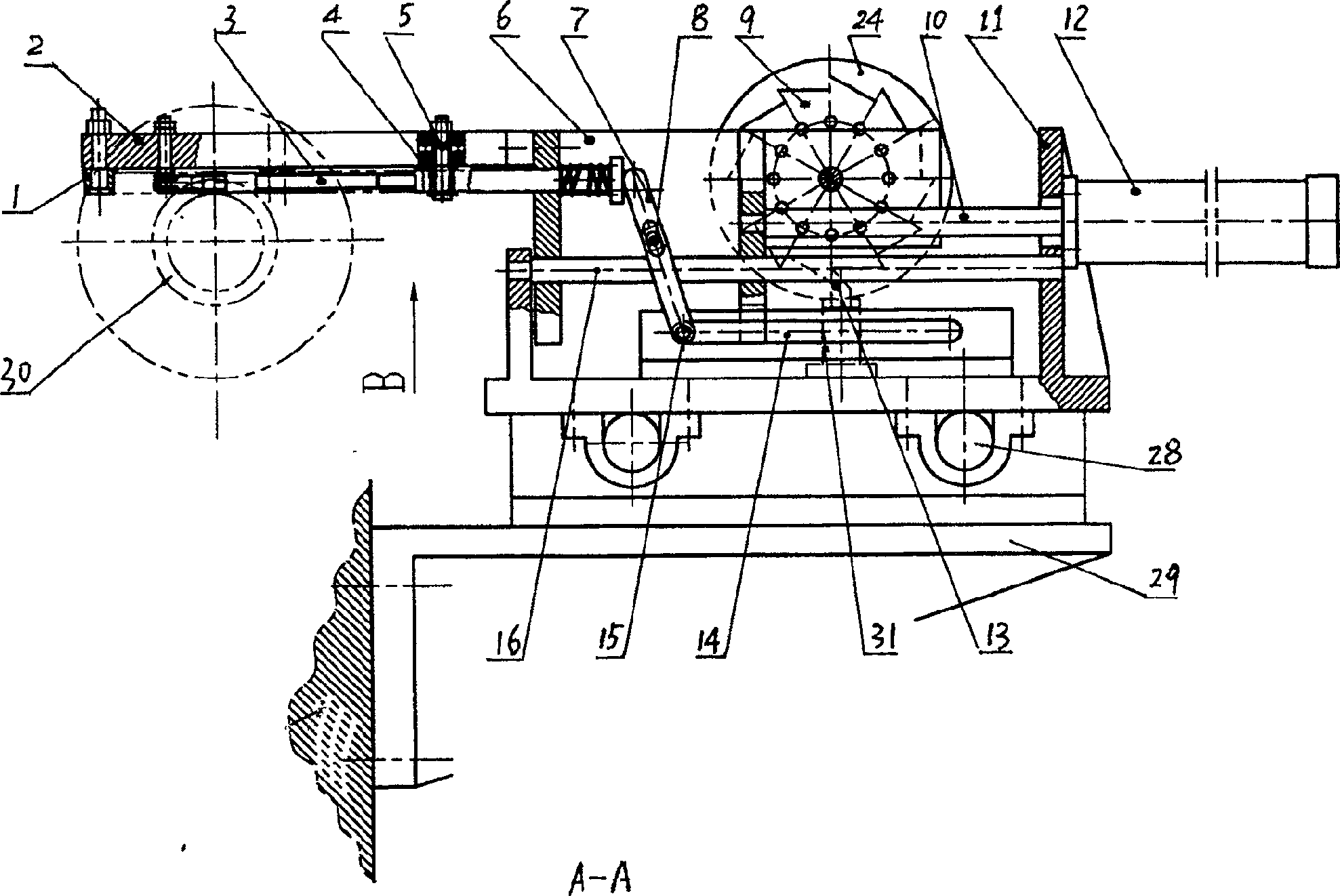
[0019] The invention relates to a crankshaft thrust surface polishing device, which mainly includes a longitudinal movement mechanism, a transverse feed tension mechanism, and a winding mechanism.

[0020] From figure 1 , figure 2 It can be seen from the figure that the longitudinal movement mechanism of the present invention mainly includes a base 11, a guide column 28, a bracket 29, etc., the guide column 28 is installed on the bracket 29 connected with the machine bed, and the whole device base 11 is installed on the guide column 28 , and can move horizontally along the longitudinal direction of the guide column 28.

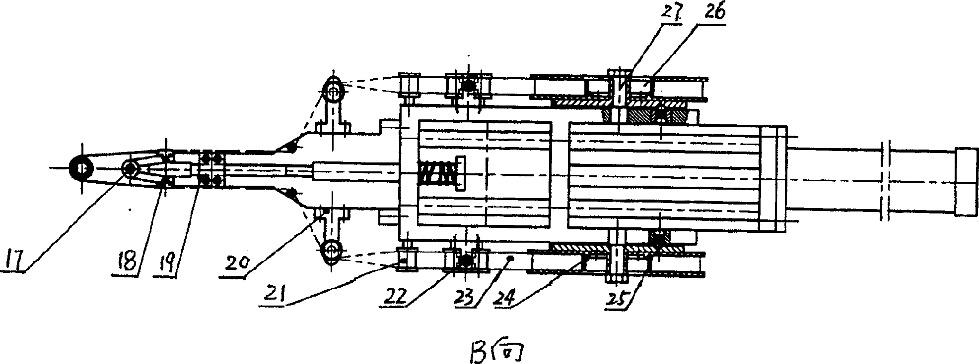
[0021] From figure 1 , figure 2 It can also be seen from the figure that the lateral feed tensioning mechanism of the present invention mainly includes a cylinder 12, a piston rod 10, a sliding support 6, a supporting plate 2, a pressure rod 7, a conical expansion rod 3, an expansion block 18, a guide rod 16, etc. . Wherein the cylinder 12 is installed ...


PUM


Abstract

The invention relates to a crankshaft thrust surface polishing device which comprises a longitudinal shifting mechanism, a transverse feeding strainer mechanism and a tape mechanism, wherein the transverse feeding strainer mechanism comprises a gas cylinder, a piston rod, a sliding supporting, a splint, a pressure rod, a taper-shaped expansion rod and an expansion block, etc. The sliding supporting moves along a guide lever arranged on the seat transversely and horizontally. The invention pushes the sliding supporting via a gas cylinder piston rod and simultaneously drives a pressure rod to press the taper-shaped expansion rod tightly to make the expansion block expand and make a sand belt cling to bilateral thrust faces. The tape mechanism comprises a sand belt, a sand belt drive wheel, a sand belt driven wheel and a ratchet wheel, wherein the sand belt drive wheel drives the ratchet wheel and tapes. The sand belt shifts from the sand belt driven wheel to the sand belt drive wheel and moves a preconcerted distance. The ratchet wheel locates via a steel ball localizer. The invention has simple operation, greatly reduced working intensity of workers, high production efficiency, safe and reliable performance, high processing smooth finish and is an ideal crankshaft thrust face buffing device.

Description

technical field [0001] The invention relates to a polishing device, in particular to a crankshaft thrust surface polishing device. Background technique [0002] We know that the crankshaft is one of the important machine parts, its structure and stress are complex, the workload is heavy, and the requirements for internal metallurgical quality, casting quality and forming precision are very high. The surface roughness of the thrust surface of the crankshaft of the automobile engine is high, and it must reach Ra≤0.4 according to the performance technical requirements. Usually, the surface roughness can only reach Ra≥0.63 after finishing. To effectively solve this problem, it must be polished. The existing crankshaft thrust surface polishing device generally adopts a special crankshaft thrust surface polishing machine, which has complex structure, high price, low work efficiency and inconvenient use. Wherein the tape take-up mechanism utilizes gear shifting to drive to reali...

Claims


Application Information

Patent Timeline
Patent Type & Authority Patents(China)
IPC IPC(8): B24B21/16
Inventor 宋文友李世松胡京开于新贵慈惟红邵诗波毕晓君李忠民刘劲松刘永友
Owner TIANRUN IND TECH CO LTD
Why Eureka
Try Eureka