High temperature sliding wear and thermal contact fatigue testing machine for material
What is Al technical title?
Al technical title is built by PatSnap Al team. It summarizes the technical point description of the patent document.
A material testing machine and thermal contact technology, applied in the direction of analyzing materials, testing wear resistance, using mechanical devices, etc., can solve the problems of difficulty in simulating production conditions, short length of rolling pieces, etc., and achieve high reliability and low cost of equipment operation. , the effect of high efficiency
Inactive Publication Date: 2009-05-13
UNIV OF SCI & TECH BEIJING
View PDF6 Cites 0 Cited by
Summary
Abstract
Description
Claims
Application Information
AI Technical Summary
This helps you quickly interpret patents by identifying the three key elements:
Problems solved by technology
Method used
Benefits of technology
Problems solved by technology
Affected by temperature, the length of the simulated rolling is short, which makes it difficult to simulate the actual production situation
Method used
Image
Click on the blue label to locate the original text in one second.
Reading with bidirectional positioning of images and text.
Examples
Embodiment
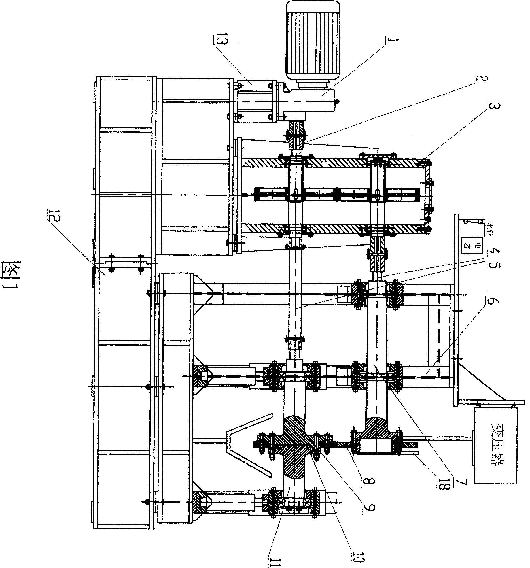
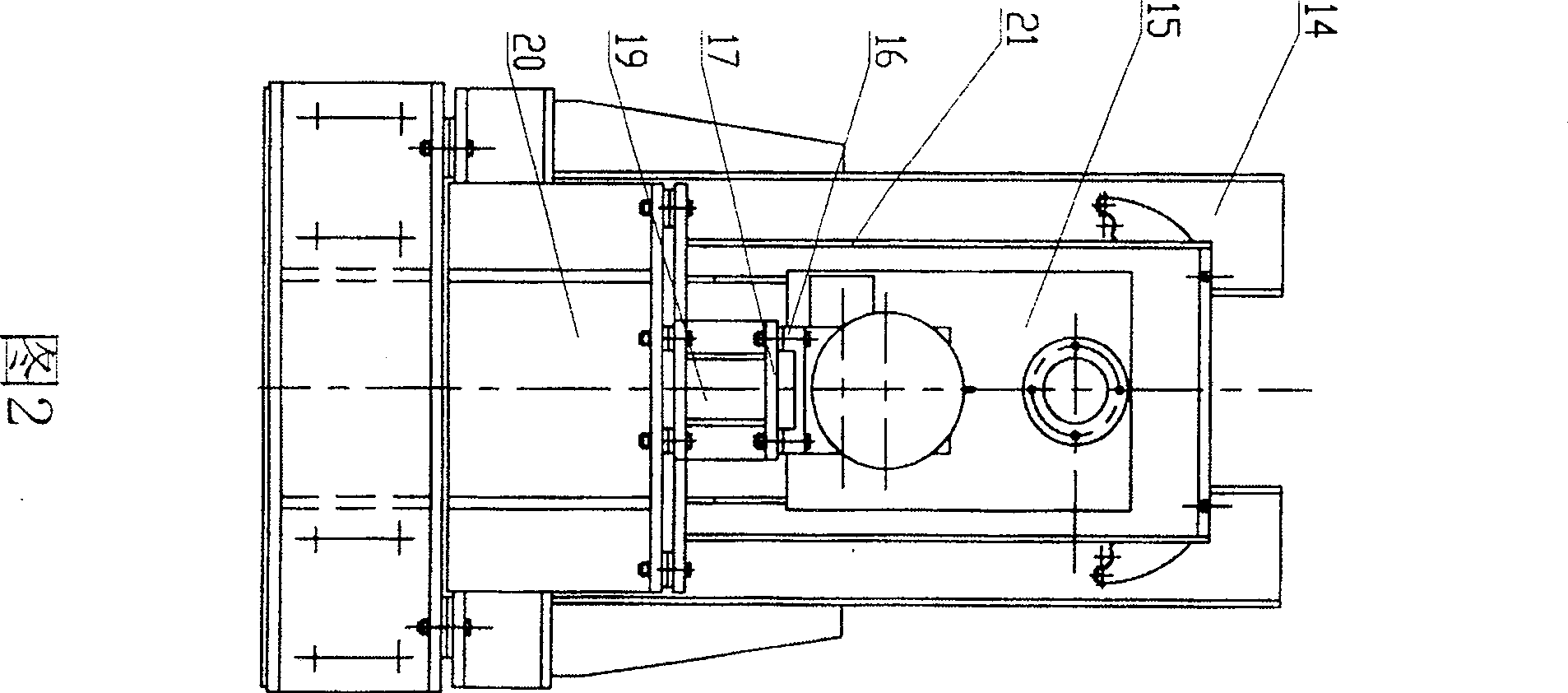
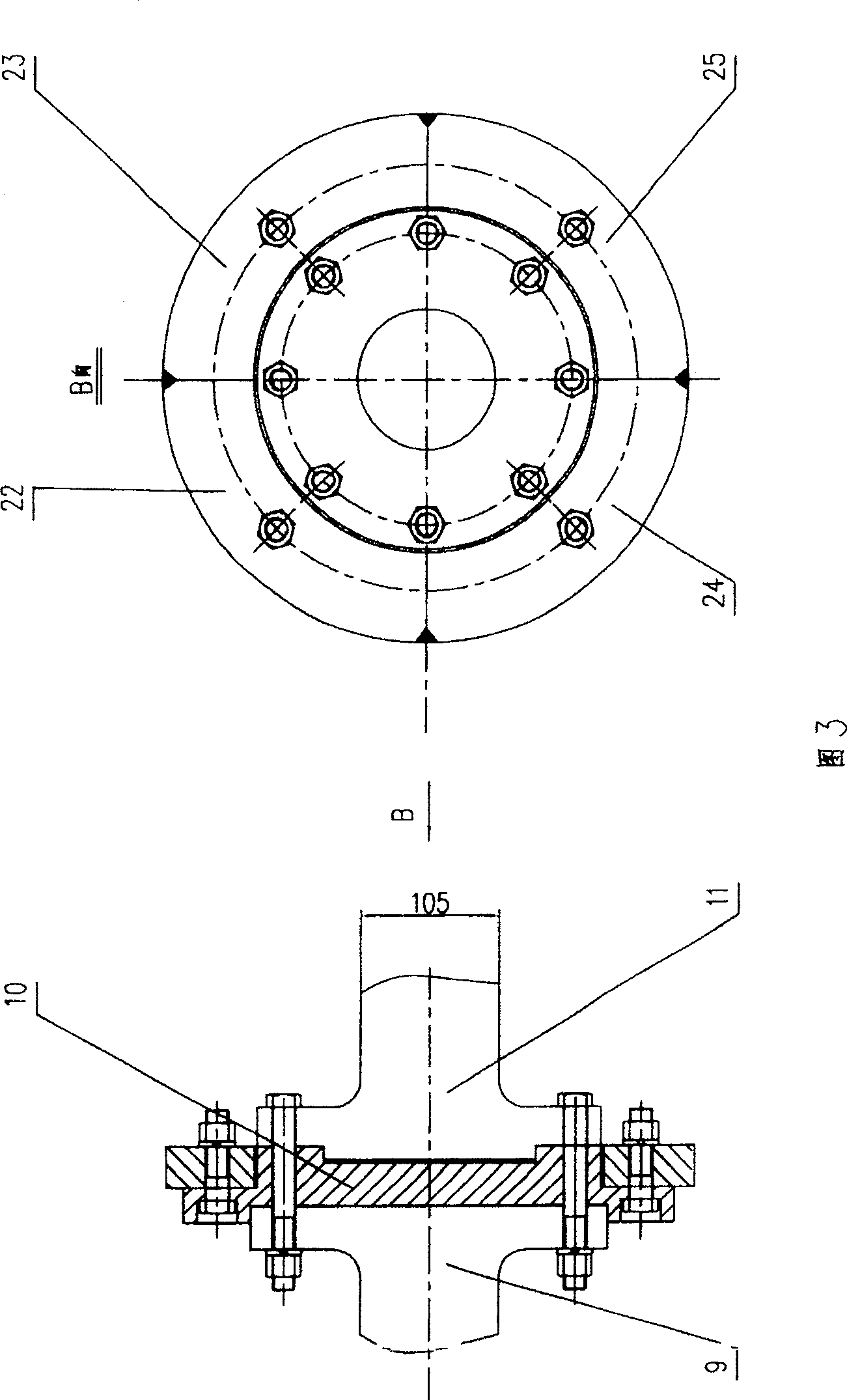
[0021] The high-temperature sliding wear and thermal contact fatigue material testing machine includes a geared motor 1, a support 13, a coupling 2, a distribution gearbox 3, a universal joint shaft 4, 5, a frame 14, an upper friction pair system 6, and a lower friction pair System lifting hydraulic cylinder 19, hydraulic cylinder connecting seat 17, hydraulic cylinder base 20, base 12, induction heating coil 18, upper friction pair system including rotary shaft 7, bearing seat 15, pressure plate 21, upper friction wheel 8, lower friction pair system It consists of a left rotary shaft 9, a chuck 10, a right rotary shaft 11, a bearing seat 16, a lower friction wheel 22, a coupling bolt 23, and a positioning plate 24. The hydraulic system includes electromagnets 26, 27 for electromagnetic reversing, and pressure gauge The electric contact relay 28, the reduction motor 1 is installed on the base 12 through the support 13, the distribution gearbox 3 is installed on the base 12, the...
PUM
Abstract
The invention is a tester for high temperature sliding abrasion and thermal contact fatigue material, belonging to the technical field of material processing and friction and abrasion testing, comprising friction auxiliary, pressure regulator, heater, and lubricating device, where the friction auxiliary comprises speed reducing motor, variable frequency speed regulating motor, supporting seat, shaft coupler, distribution gear box, universal connection shaft, machine frame, top friction auxiliary system, bottom friction auxiliary system, and friction piece, where the top friction auxiliary system comprises rotating shaft, bearing base, pressure plate, and top friction piece, the bottom friction auxiliary system comprises right and left rotating shafts, clamping chuck, bottom friction piece and bearing base, the pressure regulator comprises two groups of lift hydraulic cylinders, hydraulic pump, pressure sensing instrument and displaying instrument, the heater comprises induction heating coil, and water cooled system, the lubricating device comprises nozzle, and oil feeding system, the hydraulic system comprises electromagnetic switched electromagnet, and electric contact relay. The advantages of the invention lie in that: the equipment is simple in structure, the number of parts is small, the efficiency is high and the cost is low and it is applied to scientific research and production field simulation.
Description
Technical field [0001] The invention belongs to the technical field of material processing and wear, and in particular provides a high-temperature sliding wear and thermal contact fatigue material testing machine. It is suitable for sliding wear and contact fatigue tests between materials under high temperature conditions. Background technique [0002] (1) Among the existing wear and fatigue testing machines, there is no relative sliding wear and contact fatigue testing machine between materials at high temperature (850-1000°C), especially under hot rolling conditions, the impact of forward sliding and lubrication on high temperature Sliding wear, thermal contact fatigue influence test. [0003] (2) There are many types of wear testing machines available. These testing machines are mostly used to measure the coefficient of friction under different lubrication and temperature conditions. The common ones are disc-type testing machines, four-ball friction testing machines, and...
Claims
Application Information
Patent Timeline
Application Date:The date an application was filed.
Publication Date:The date a patent or application was officially published.
First Publication Date:The earliest publication date of a patent with the same application number.
Issue Date:Publication date of the patent grant document.
PCT Entry Date:The Entry date of PCT National Phase.
Estimated Expiry Date:The statutory expiry date of a patent right according to the Patent Law, and it is the longest term of protection that the patent right can achieve without the termination of the patent right due to other reasons(Term extension factor has been taken into account ).
Invalid Date:Actual expiry date is based on effective date or publication date of legal transaction data of invalid patent.