Loading system and method for loading substrates with electrical components

A technology for assembling systems and parts, applied to electrical components, electrical components, etc., can solve the problems of increasing swing, increasing structure, investment in economy and control technology, increasing idle length of guide beams, etc., and achieves the effect of stabilizing the supporting structure

Inactive Publication Date: 2009-05-20
ASM ASSEMBLY SYST GMBH & CO
View PDF3 Cites 0 Cited by
  • Summary
  • Abstract
  • Description
  • Claims
  • Application Information

AI Technical Summary

Problems solved by technology

[0003] The above-mentioned assembly system has such a disadvantage because both ends of the guide beam are fixed, that is, if the guide beam is driven at one end, it is difficult to quickly and accurately position the assembly device on the base; Driving at both ends will increase the investment in structure, economy and control technology
Also, using a larger base increases the idle length of the guide beam, which increases the potential for wobble in the case of a heavy boom with a mid-section arrangement

Method used


Image

  • Loading system and method for loading substrates with electrical components
  • Loading system and method for loading substrates with electrical components
  • Loading system and method for loading substrates with electrical components

Examples


Embodiment Construction

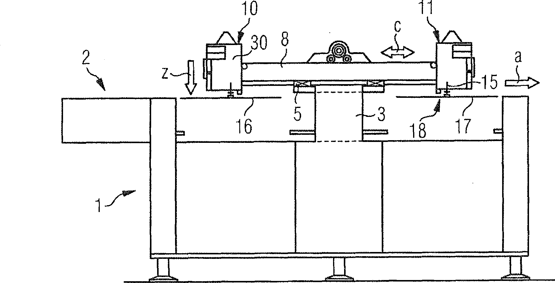
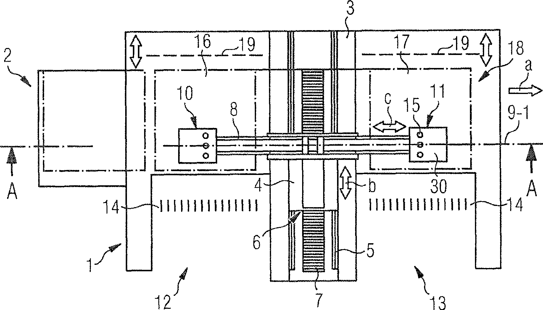
[0035] Figures 1a and 1b are schematic representations of an embodiment of the assembly system of the present invention. The assembly system has a base frame 1 on which a transport line 2 for transporting substrates in a transport direction (arrow a) is arranged. Wherein, the conveying line can be, for example, a simple conveying belt with a driving mechanism. A main support 3 of the assembly system is arranged in such a way that it spans the conveying line 2 like a bridge in a direction perpendicular to the conveying direction. Arranged on the main carrier 3 is a first bearing carriage 4 which is displaceable in a movement direction (arrow b) perpendicular to the conveying direction. Wherein, the first support slide 4 moves along the main support 3 under the guidance of the corresponding linear guide device 5 and is driven, for example, by a first linear motor 6 . Arranged on the main carrier 3 are permanent magnets 7 serving as the stationary part of the first linear motor...


PUM


Abstract

Loading system and method for loading substrates with electrical components. A loading system for loading substrates with electrical components comprises at least one transporting line (2), by means of which a first and a second substrate (16, 17) can be transported in a transporting direction, a basic carrier (3), a first carrier slide (4), which is mounted on the basic carrier (3) displaceably in a displacing direction, an elongated first carrier arm (8), the longitudinal axis (9-1) of which is oriented transversely in relation to the displacing direction and which is mounted on the first carrier slide (4) displaceably in the direction of its longitudinal axis (9-1), and a first loading head (10) and a second loading head (11), which are arranged at a fixed distance from each other on the first carrier arm (8) on opposite sides of the carrier slide in the direction of the longitudinal axis (9-1) of the first carrier arm (8).

Description

technical field [0001] The invention relates to an assembly system for equipping a substrate with electrical components and a corresponding method carried out using said assembly system. Background technique [0002] WO 03 / 103363 discloses a mounting system which has an arm on which are fastened two mounting devices at a fixed distance from one another. The support arm is movable along a guide beam in a conveying direction of the substrate to be assembled. Both ends of the guide beam are supported by two fixed main brackets, and the guide beam can move perpendicular to the moving direction of the support arm. [0003] The above-mentioned assembly system has such a disadvantage because both ends of the guide beam are fixed, that is, if the guide beam is driven at one end, it is difficult to quickly and accurately position the assembly device above the base; Driving at both ends will increase the investment in structure, economy and control technology. In addition, using a ...

Claims


Application Information

Patent Timeline
Patent Type & Authority Patents(China)
IPC IPC(8): H05K13/04
CPCH05K13/0452H05K13/0404H05K13/0411
Inventor 穆罕麦德·米戴安波尔
Owner ASM ASSEMBLY SYST GMBH & CO
Why Eureka
Try Eureka