Switch of electric tool

A technology of electric tools and switches, which is applied in the field of electric switches, can solve problems such as shortening the service life of switches, rising temperature, and aging of contact points, and achieves the goals of reducing the possibility of thermal deformation, good safety and reliability, and prolonging service life Effect

Active Publication Date: 2009-06-03
CHANGZHOU YUNJIE ELECTRIC
View PDF5 Cites 0 Cited by
  • Summary
  • Abstract
  • Description
  • Claims
  • Application Information

AI Technical Summary

Problems solved by technology

[0002] At present, the power tool switches on the market are all single-circuit. When a single-circuit switch passes a large current during operation, the current is very large at the moment of on and off, and a strong electric spark will appear between the switch contacts. Causes a large electric corrosion phenomenon to the contact point of the switch, aging the contact point and finally destroying the switch
In addition, the single-circuit switch has a large current during the power-on operation process. When a large current passes through the switch, the contact piece of the switch will heat up, and the heat will be transferred to the plastic support that is in contact with the contact piece, causing the temperature of the plastic support to rise. , when the temperature rises to a certain level, the plastic support will be deformed due to high temperature, which will cause the contact piece to shift and make the switch invalid, which not only shortens the service life of the switch, but also poses a safety hazard

Method used


Image

  • Switch of electric tool
  • Switch of electric tool
  • Switch of electric tool

Examples


Embodiment Construction

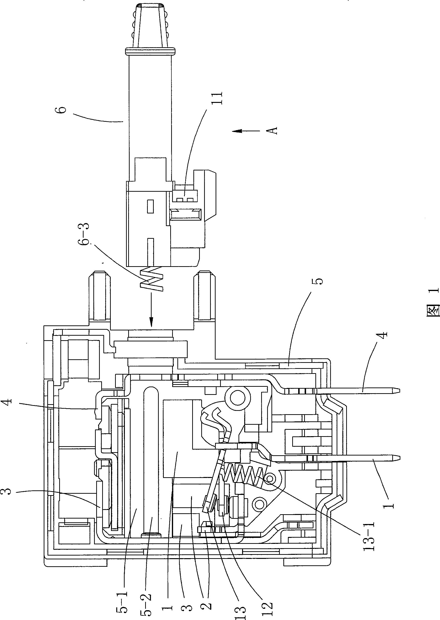
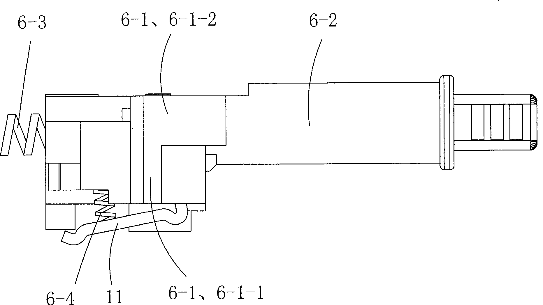
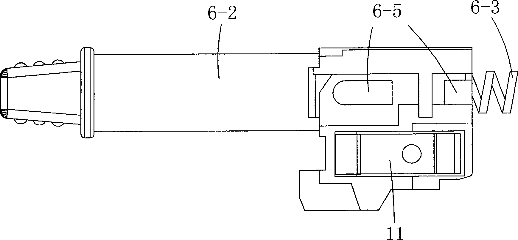
[0022] See Figure 1 to Figure 7 , the electric tool switch includes a housing 5 and a switch arm 6 with one end protruding from the housing 5. On the inner bottom wall of the housing 5, a first static contact piece 1, a second static contact piece 2, and a third static contact piece are vertically arranged. Contact 3 (respectively see Figure 4 , 5 , 6), the wire connection ends of the first static contact piece 1 and the third static contact piece 3 all extend out of the housing 5 and the first static contact piece 1 is connected to the negative pole of the power supply; in addition, the housing 5 is also provided with a second Four static contacts 4 (see Figure 7 ), the fourth static contact piece is connected to the positive pole of the power supply, and one end of the fourth static contact piece 4 extends out of the housing 5 . A transverse channel 5-1 is provided in the housing 5, and the switch arm 6 is arranged in the channel 5-1. The switch arm 6 includes a base b...


PUM


Abstract

The invention discloses an electromotion tool switch that comprises shell and a switch one end of which extends out of the shell, the first, the second, the third static contactor are set at the bottom of the shell, besides, the forth static contactor is set in the shell; the shell possesses landscape orientation channel, said switch arm is set in the channel, the first dynamic contactor which is contacted with the first static contactor is set on bottom of the switch arm, the turn part of the first static contactor which is at side of the switch arm is connected with the second and the third dynamic contactor which are corresponding with the second and the third static contactor, boss id set on the side surface of the switch arm, during the movement of the switch, the first dynamic contactor is contacted with the second and the third static contactor, synchronously, the switch arm can control the contact between the second and the third dynamic contactor and the corresponding second and the third static contactor. The switch possesses two independent loops, and it is two-contactor contact, it can branch off, and decreases the radiation, the reliability of switch is good, the service life is extended.

Description

technical field [0001] The invention relates to an electric switch, in particular to an electric tool switch with double circuits. Background technique [0002] At present, the electric tool switches on the market are all single-circuit. When a single-circuit switch passes a large current during operation, the current is very large at the moment of on and off, and a strong electric spark will appear between the switch contacts. It causes a large electric corrosion phenomenon to the contact point of the switch, which makes the contact point age and finally damages the switch. In addition, the single-circuit switch has a large current during the power-on operation process. When a large current passes through the switch, the contact piece of the switch will heat up, and the heat will be transferred to the plastic support that is in contact with the contact piece, causing the temperature of the plastic support to rise. , when the temperature rises to a certain level, the plasti...

Claims


Application Information

Patent Timeline
Patent Type & Authority Patents(China)
IPC IPC(8): H01H21/18H01H21/22
Inventor 储云跃
Owner CHANGZHOU YUNJIE ELECTRIC
Why Eureka
Try Eureka