Press die apparatus for thin plate and press forming method
A thin plate stamping and forming method technology, which is applied in the field of thin plate stamping die device and stamping forming, can solve the problems of difficult anti-wrinkle load, difficult to obtain anti-wrinkle load in advance, and lower production efficiency
- Summary
- Abstract
- Description
- Claims
- Application Information
AI Technical Summary
Problems solved by technology
Method used
Image
Examples
Embodiment 1
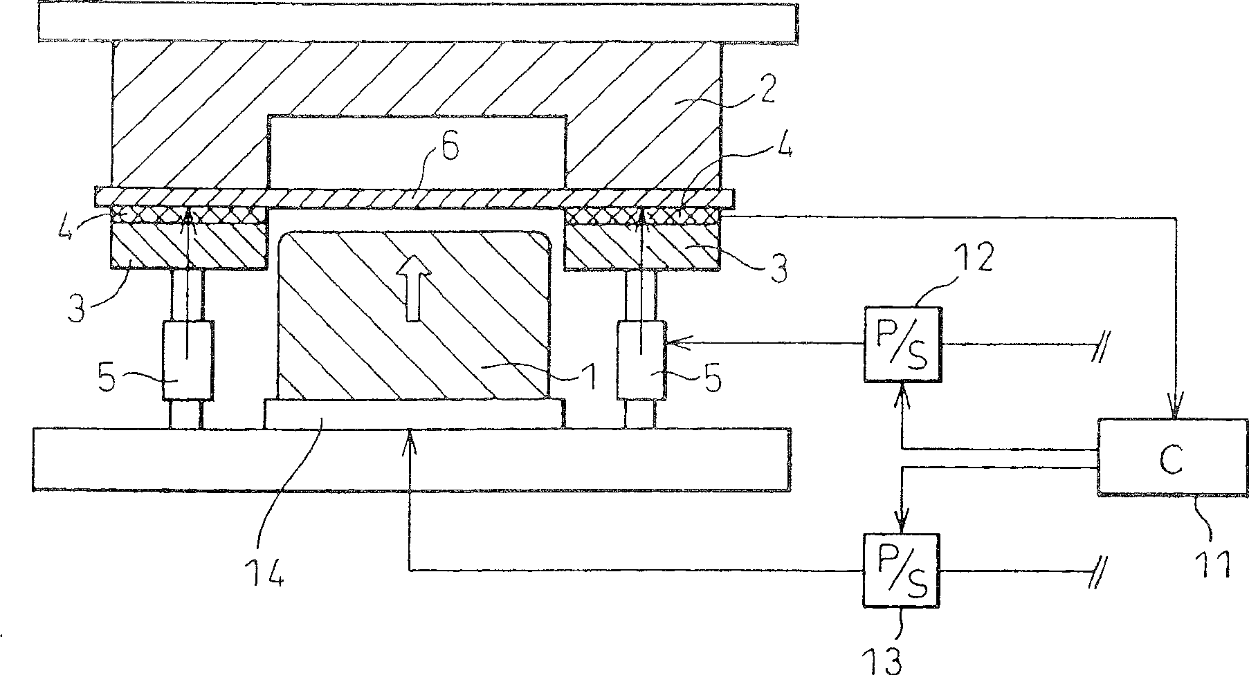
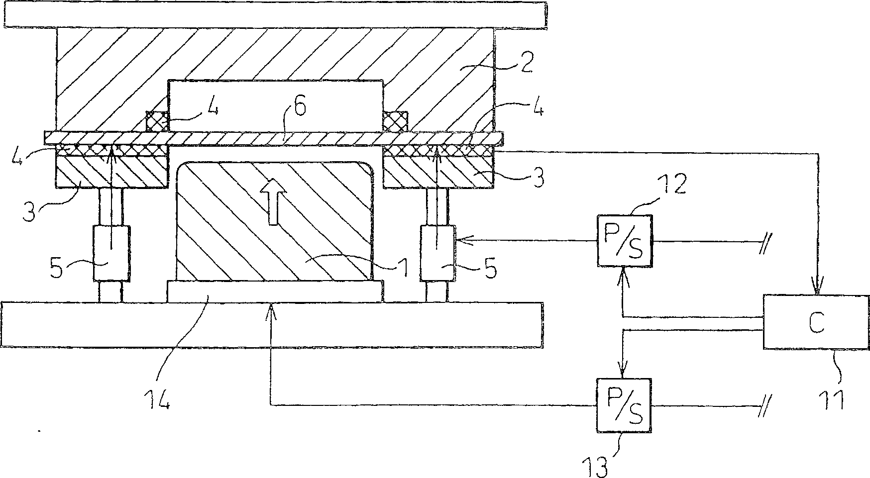
[0109] Based on the above invention, a trial figure 1 The die set shown is an example of the present invention, and press forming using a thin steel plate was performed. A piezoelectric element was used as the friction force measuring member 4, and surface-hardened S45C was used for the flat plate 7.
[0110] Table 1 shows the characteristics of the steel sheets used. Alloy fusion (hot-dip) galvanized steel sheets with a plate thickness of 1.2 mm were used, and two types of steel sheets with different alloy degrees were used.
[0111] Table 1
[0112] Material Yield stress [MPa] Tensile strength [MPa] Elongation [%] A (high alloy degree) 187 310 48 B (small alloy degree) 175 314 49
[0113] Forming test Continuous deep drawing of 50mm×50mm rectangular parts was carried out, and the forming load at this time and whether the formed product was broken or wrinkled were checked. Use a square material consisting of 100mm x 100mm, for example ...
Embodiment 2
[0122] Based on the above invention, a trial Figure 5 The die set shown is an example of the present invention, and press forming using a thin steel plate was performed. A thermocouple was used as the temperature sensor 10, and surface-hardened S45C was used for the plate 7.
[0123] The steel plate used in the experiment was the same as that used in Example 1.
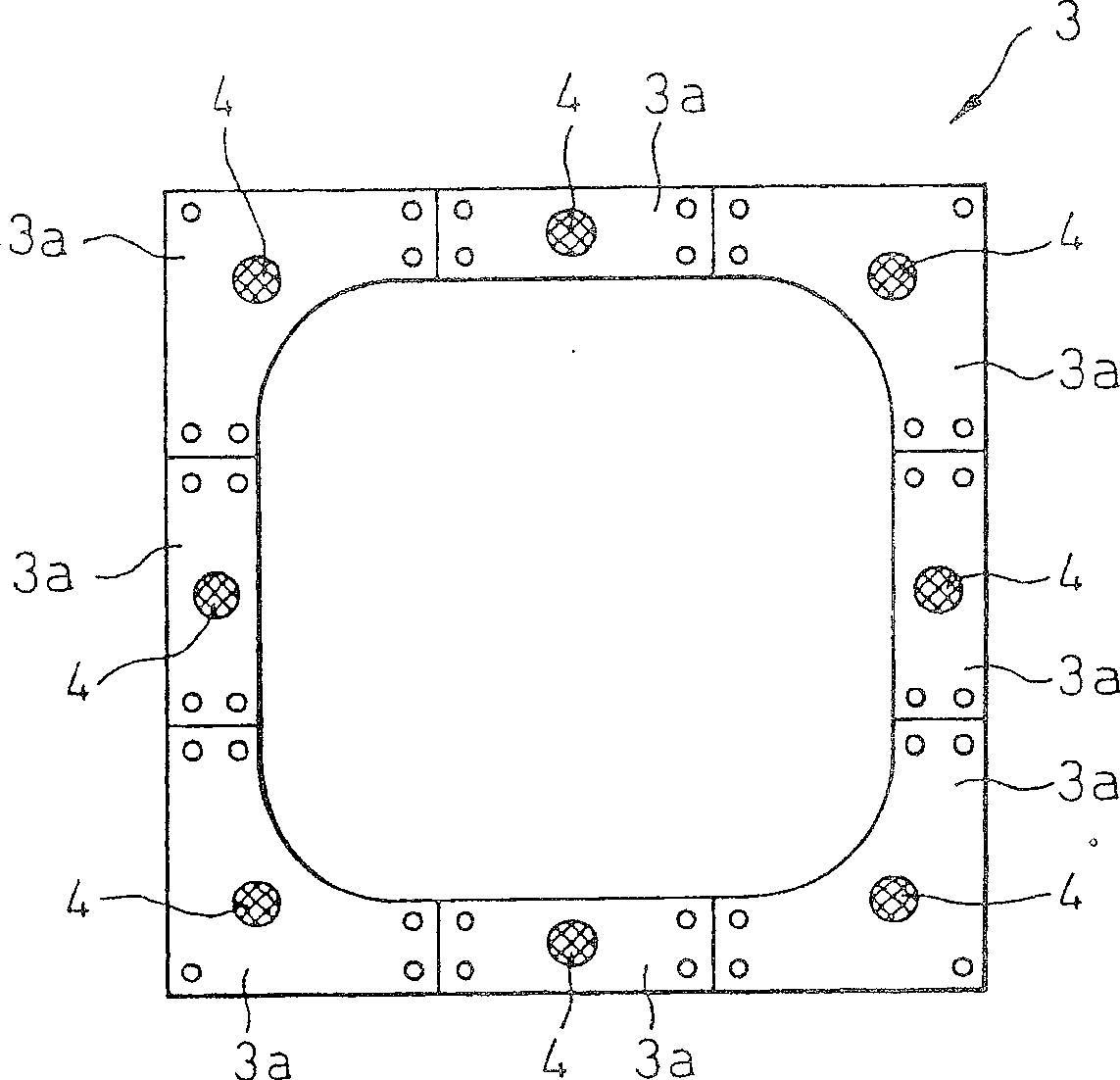
[0124] Forming test The 50mm×50mm rectangular piece (square tube) was continuously drawn and formed, and the forming load at this time and whether the formed product was broken or wrinkled were checked. Use a square material (plain board) of 100mm×100mm, for example Figure 6 The shown anti-crease mold consisting of 8 mold parts 3a was subjected to forming tests.
[0125] Table 4 shows the results of 100 consecutive molding tests.
[0126] A comparative example is the same as in Example 1.
[0127] Table 4
[0128]
[0129] In Example 3 of the present invention in which all mold parts were molded at a consta...
Embodiment 3
[0131] Based on the above invention, a trial Figure 8 The die set shown is an example of the present invention, and press forming using a thin steel plate was performed. A strain gauge was used as the stamping reaction force measurement member 9, and surface-hardened S45C was used for the flat plate 7.
[0132] The steel plate used in the experiment was the same as that used in Example 1.
[0133] Forming test Continuous deep drawing of 50mm×50mm rectangular parts was carried out, and the forming load at this time and whether the formed product was broken or wrinkled were checked. Use a square material (plain board) of 100mm×100mm, for example image 3 The shown anti-crease mold consisting of 8 mold parts 3a was subjected to forming tests.
[0134] Table 5 shows the results of 100 consecutive molding tests.
[0135] A comparative example is the same as that of Example 1.
[0136] table 5
[0137]
[0138] In Example 5 of the present invention, in which the pressure o...
PUM
 Abstract
Description
Claims
Application Information
 - R&D
- Intellectual Property
- Life Sciences
- Materials
- Tech Scout
- Unparalleled Data Quality
- Higher Quality Content
- 60% Fewer Hallucinations
Browse by: Latest US Patents, China's latest patents, Technical Efficacy Thesaurus, Application Domain, Technology Topic, Popular Technical Reports.
© 2025 PatSnap. All rights reserved.Legal|Privacy policy|Modern Slavery Act Transparency Statement|Sitemap|About US| Contact US: help@patsnap.com


