Audio reproducing apparatus

A reproduction device and sound technology, applied in speech analysis, speech synthesis, stereo system, etc., can solve problems such as non-existent implementation methods

Active Publication Date: 2009-06-24
PANASONIC CORP
View PDF2 Cites 0 Cited by
  • Summary
  • Abstract
  • Description
  • Claims
  • Application Information

AI Technical Summary

Problems solved by technology

[0013] In any case, when synthesizing audio signals of multiple data and reproducing them, it is necessary to synchronize and reproduce the multiple audio signals, but there has been no method of realizing this until now.

Method used


Image

  • Audio reproducing apparatus
  • Audio reproducing apparatus
  • Audio reproducing apparatus

Examples


Embodiment approach 1

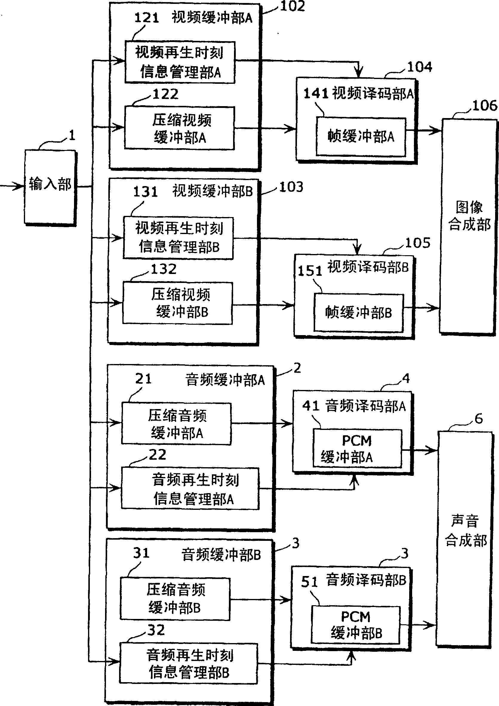
[0059] First, mainly refer to the block diagram showing the configuration of the audiovisual reproduction device according to Embodiment 1. figure 2 , the configuration of the video and audio reproduction device according to Embodiment 1, the video reproduction method, and the audio reproduction method will be described. In addition, although the present invention relates to a technique for synchronizing and reproducing a plurality of digital audio signals, before describing this technique in detail, a technique for reproducing a multiplexed signal of a video signal and an audio signal will be described. .

[0060] figure 2 It is a block diagram showing the configuration of the audiovisual reproduction device according to the first embodiment. The image and sound reproducing device of Embodiment 1 is a device for reproducing a signal obtained by multiplexing a video signal and an audio signal, such as figure 2 As shown, it includes: input unit 1, video buffer unit A102, ...

Embodiment approach 2

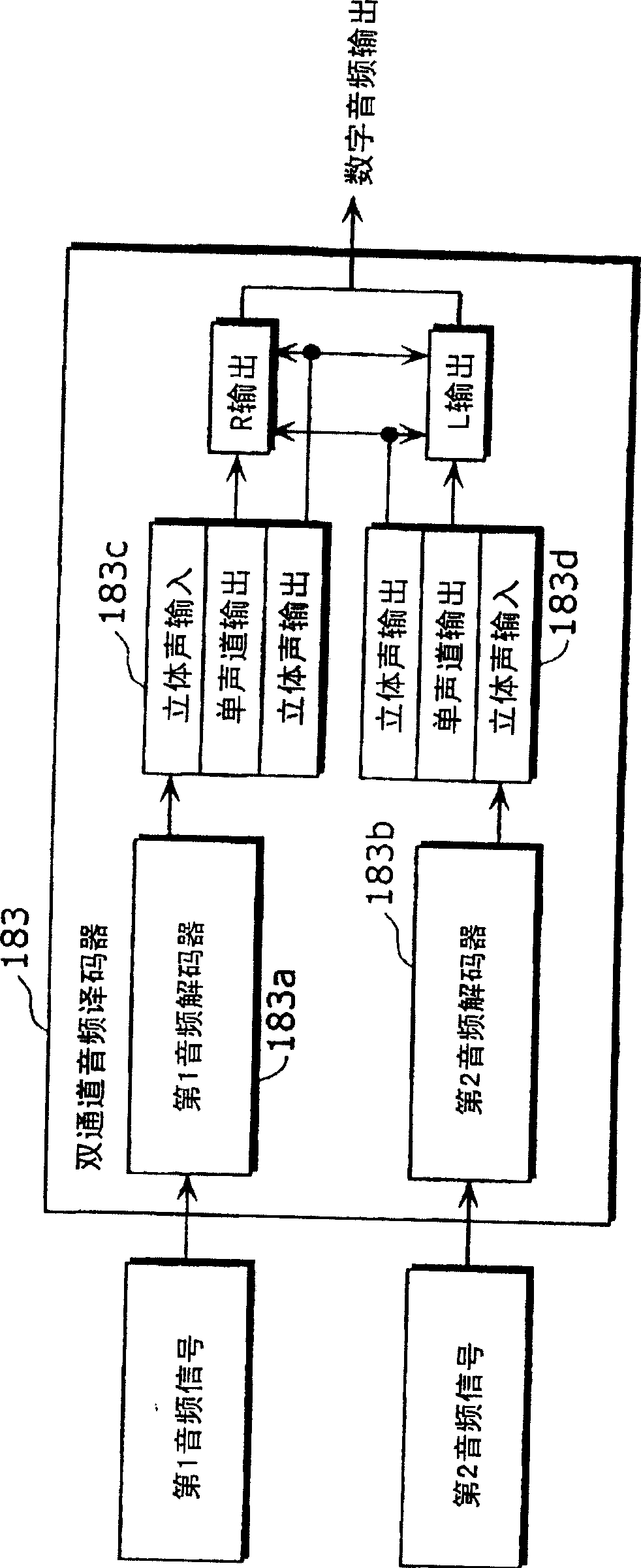
[0149] The following mainly refers to the block diagram showing the configuration of the sound reproduction device according to Embodiment 2. Figure 8 The configuration of the sound reproduction device and the sound reproduction method according to Embodiment 2 will be described.

[0150] In Embodiment 1, a method of realizing AV synchronization of a plurality of audios and a plurality of images with reference to the system time reference STC has been described. In Embodiment 2, as a method of AV synchronization, the audio reproduction device separates a plurality of audio signals from the input compressed audio data, reads the respective audio reproduction time information, and executes the main function based on the audio reproduction time information of one audio signal. The audio signal is decoded, and the audio reproduction time information of the other audio signal is matched with the audio reproduction time information of the main audio signal and decoded, thereby acqu...

Embodiment approach 3

[0179] The following mainly refers to the block diagram showing the configuration of the sound reproduction device according to Embodiment 3. Figure 8 , and the structure of the audio output processing section that performs variable speed control Figure 21 , the configuration of the sound reproduction device and the sound reproduction method according to Embodiment 3 will be described.

[0180] The audio output processing unit 61 is not limited to performing variable-speed playback processing. For example, a process of changing the pitch of the decoded voice may be performed. When a digital playback signal is received and recorded, and at least the encoded audio stream is synchronized and reproduced, after the audio decoding process, it is selected based on the synchronization information before or after the audio synthesis process and extracted from the data. voice information and reproduce it. In this way, for example, after adding the sub-sound to the main sound, the p...


PUM


Abstract

The present invention provides a sound reproduction device for synchronously reproducing a plurality of digital sound signals. The sound reproduction device includes a synchronization setting unit (11) and a sound synthesis unit (6). In the state of holding, a plurality of audio reproduction time information of each of the plurality of audio signals is allocated to one time axis to synchronize the plurality of audio signals, and the sound synthesis unit (6) utilizes the time information allocated to the above-mentioned time axis. A plurality of pieces of audio reproduction time information is used to synthesize a plurality of audio signals.

Description

technical field [0001] The present invention relates to a sound reproducing device, which regenerates compressed and coded digital sound signals. Background technique [0002] In recent years, a playback device has been widely used. This playback device reads and decompresses digital audio and video signals that are compressed and recorded on various recording media such as CD-ROM, DVD-ROM, and hard disks, and transmits them through a display connected to itself. and speakers to reproduce the decompressed signal. [0003] Also, apparatuses for recording and reproducing compressed digital audio signals and video signals such as BS digital broadcasting, CS digital broadcasting, and terrestrial digital broadcasting are widespread. [0004] As a known specification for encoding audio signals and video signals into digital signals and compressing them, and then decoding the signals, MPEG is known. In order to synchronize and reproduce the audio signal and video signal after dec...

Claims


Application Information

Patent Timeline
IPC IPC(8): G11B20/10G10L19/00G11B27/10H04N5/93H04N7/52H04N7/62H04N21/2368H04N21/43H04N21/434H04S1/00
CPCH04S1/007G10L19/16G11B27/105G11B2020/10592G11B20/10G10L19/008G11B27/10H04N21/4307H04N21/2368H04N21/4341H04N21/4305H04N21/43072G10L13/02
Inventor 藤本和生冈田智之片山大朗
Owner PANASONIC CORP
Why Eureka
Try Eureka