
Digital Compensation of Analog Volume Control Gain in a Digital Audio Amplifier

a digital audio amplifier and gain compensation technology, applied in the field of digital audio systems, can solve the problems of inability to accurately achieve the instantaneous performance of this adverse effects on the sound fidelity of the digital audio system at lower volumes, and inability to adjust the instantaneous performance of the analog volume control arrangement,

Active Publication Date: 2008-05-29
TEXAS INSTR INC
View PDF5 Cites 78 Cited by
  • Summary
  • Abstract
  • Description
  • Claims
  • Application Information

AI Technical Summary

Benefits of technology

[0015]It is therefore an object of this invention to provide a volume control circuit and method of controlling volume, for a digital audio system, in which the fidelity of the audio signal, even in soft passages, is maintained.
[0017]It is a further object of this invention to provide such a circuit and method that can be readily implemented into modern digital audio systems without requiring external components or different manufacturing technologies.
[0018]It is a further object of this invention to provide such a circuit and method that is compatible with, and thus does not require changes in, the digital audio stream or processing.
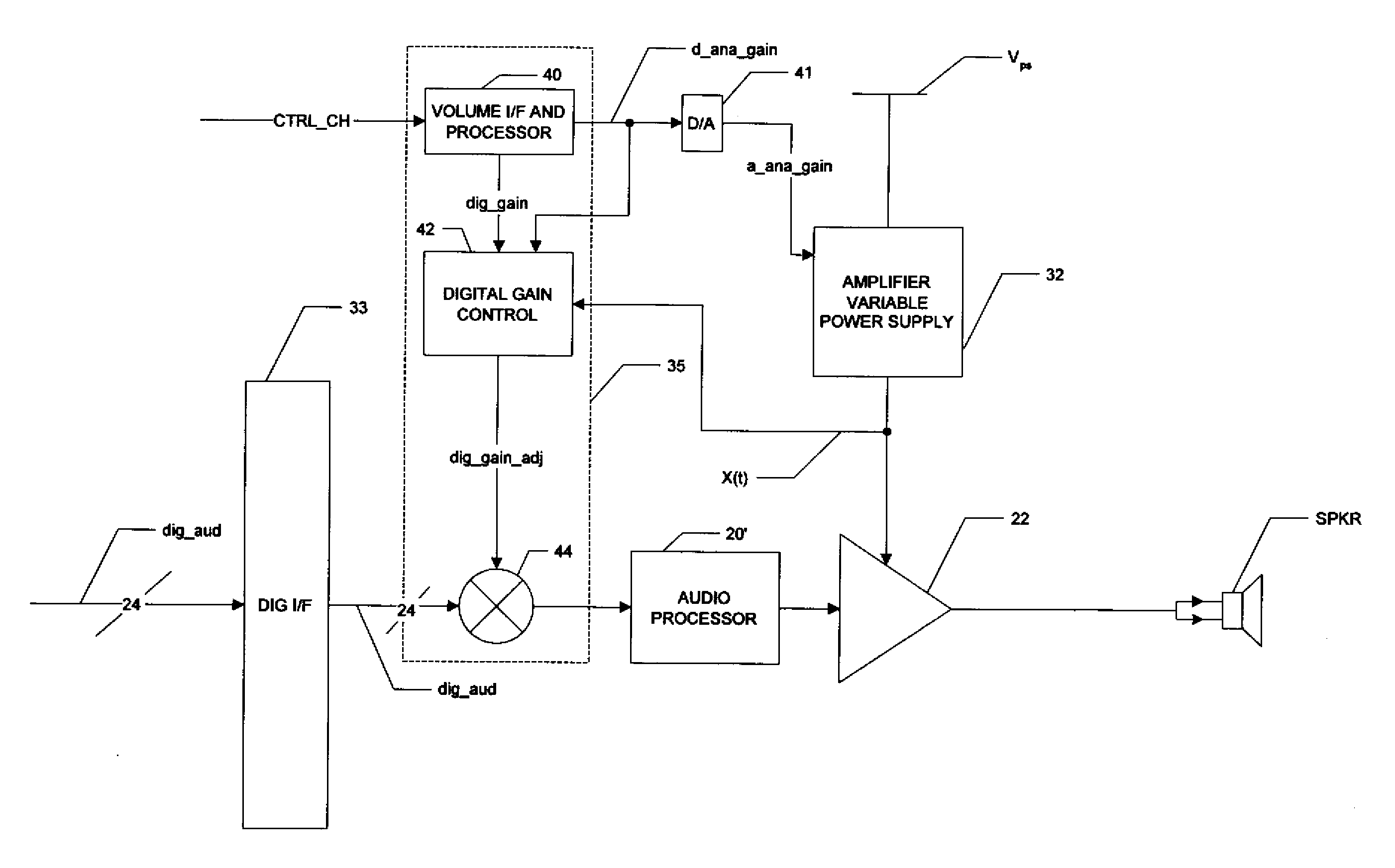
[0021]The present invention may be implemented into a volume control system in a digital audio system, and method of operating the same, in which both analog and digital controls are used. Analog control is applied to a variable power supply, which biases and thus controls a variable gain digital amplifier that drives the output stage and thus the speaker. According to one embodiment of the invention, a digital gain control circuit monitors the output of the variable power supply and, responsive to a difference between the requested volume level and the output of the variable power supply, applies a digital attenuation (e.g., multiplication of the digital word applied to the amplifier by a gain value) to the digital audio signal. Upon the output of the variable power supply matching the requested volume level, the digital attenuation is removed. In another embodiment of the invention, the digital gain control circuit applies digital attenuation to the digital audio signal for a duration and at a level based on modeling or characterization of the response of the system to changes in the requested volume levels. In another embodiment of the invention, the volume control signal is slowed by a slew-rate controller so that, in decreasing volume situations, the control signal applied to the variable power supply exhibits approximately the response of the variable power supply; the slowed output signal from the slew-rate controller controls the digital attenuation, rather than a measurement of the analog power supply voltage itself. According to this invention, therefore, instantaneous volume control appears at the digital audio system output, while minimizing the loss of information and fidelity in the signal, and without requiring shunt load devices.

Problems solved by technology

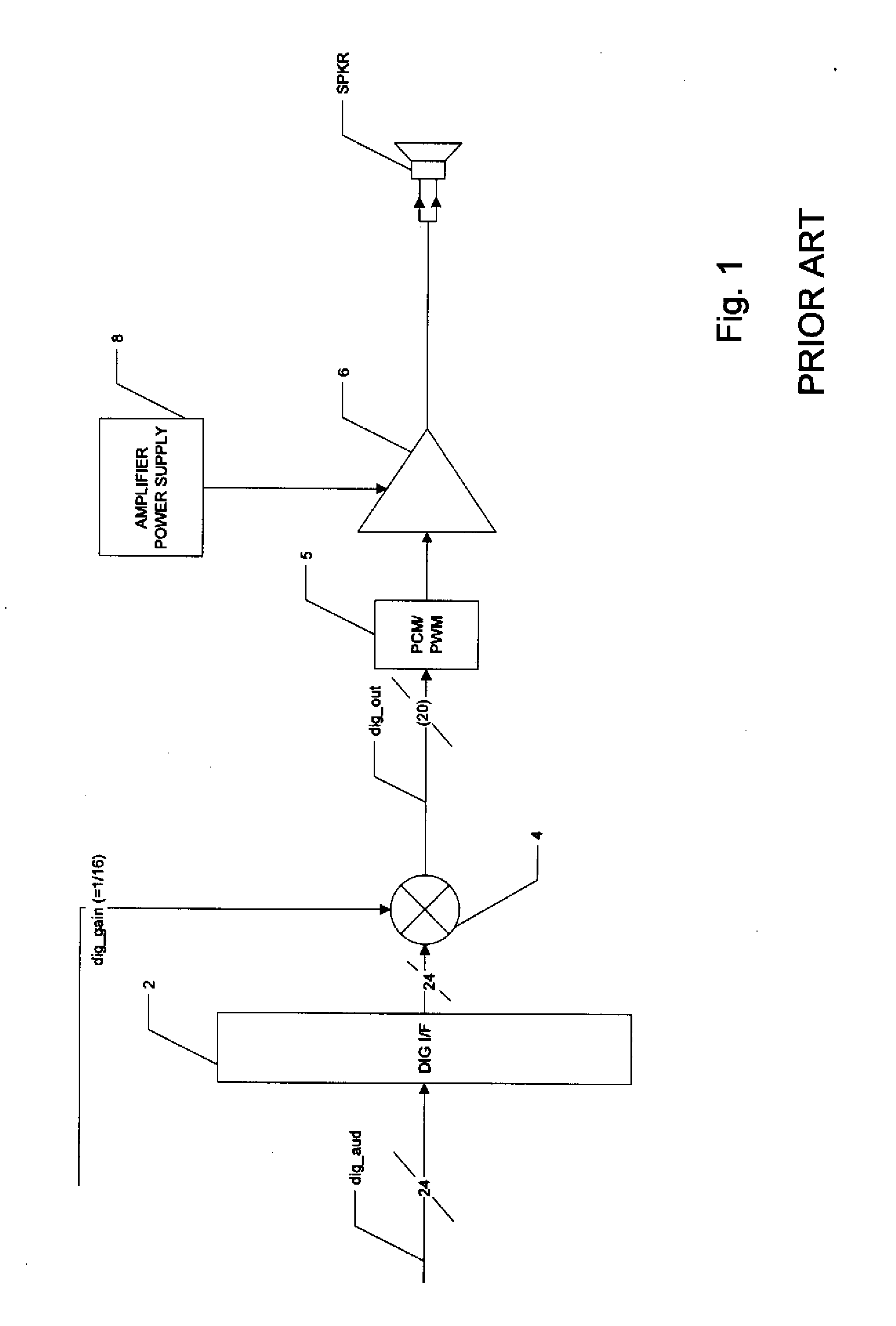
Accordingly, the sound fidelity of the digital audio system at lower volumes, especially as applied to soft passages, is adversely affected by this digital volume control approach.
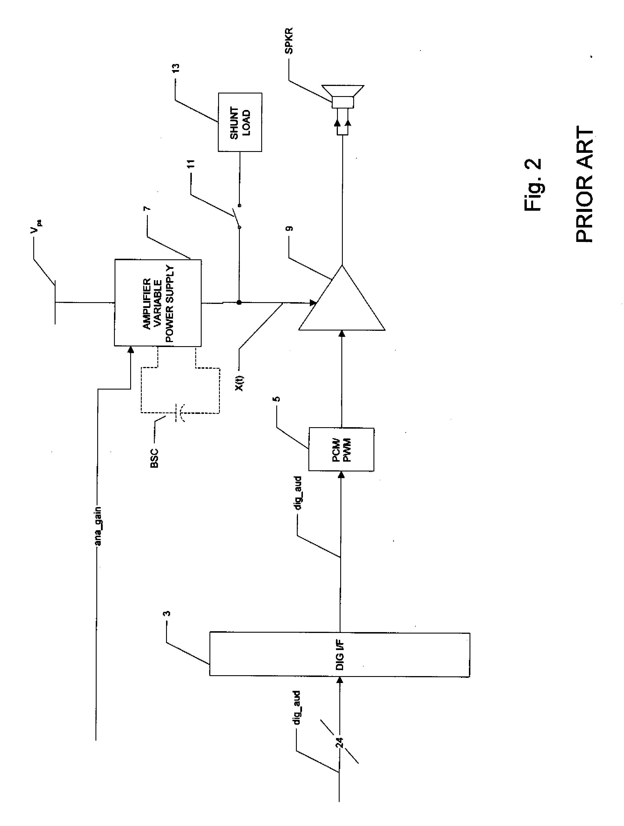
However, it has been observed that the instantaneous performance of this analog volume control arrangement is inaccurate as the volume is reduced, as will now be described.
This undesirable data-dependent lag in volume reduction is, of course, noticeable to the listener.
Rapid volume changes that cause frequent closing of switch 11, and thus a relatively large amount of current into shunt load 11 over time, will thus generate substantial heat in the system, which is especially undesirable in portable digital audio systems, which are miniaturized as much as practicable.

Method used


Image

  • Digital Compensation of Analog Volume Control Gain in a Digital Audio Amplifier
  • Digital Compensation of Analog Volume Control Gain in a Digital Audio Amplifier
  • Digital Compensation of Analog Volume Control Gain in a Digital Audio Amplifier

Examples


Embodiment Construction

[0031]The present invention will be described in connection with its preferred embodiment, namely as implemented into a digital audio receiver with a switching power stage, because it is contemplated that this invention is especially beneficial when utilized in such an application. However, it is contemplated that other applications may also benefit from this invention. Accordingly, it is to be understood that the following description is provided by way of example only, and is not intended to limit the true scope of this invention as claimed.

[0032]Referring now to FIG. 3, the construction of audio processing circuitry in digital audio receiver 10 according to the preferred embodiments of the invention will now be described. Receiver 10 may be implemented into an audio-video receiver, in which case video data paths (not shown) will also be provided, substantially in parallel with the audio processing functions shown in FIG. 3. In the example of receiver 10, multiple sources of audio...


PUM


Abstract

A digital audio system including a combination of analog and digital volume control is disclosed. A variable power supply voltage biases a power amplifier for each channel, and applies a bias voltage corresponding to an analog volume control signal. In one disclosed embodiment, digital gain control circuitry compares the bias voltage with the level expected for the analog volume control signal; if the bias voltage has not dropped in response to a reduction in the analog volume control signal, the digital gain control circuitry reduces the digital gain of the input digital audio signal, until the bias voltage responds to the reduced volume. In another disclosed embodiment, modeling or characterization of the audio system is used to derive a digital gain control signal based on the desired volume signal and the amplitude of the digital audio signal itself. In another disclosed embodiment, a slew rate limiter slows the rate of change of the control signal applied to the variable power supply, in which case the slowed control signal is used in the comparison or calculations of the reduced digital gain.

Description

CROSS-REFERENCE TO RELATED APPLICATIONS[0001]Not applicable.STATEMENT REGARDING FEDERALLY SPONSORED RESEARCH OR DEVELOPMENT[0002]Not applicable.BACKGROUND OF THE INVENTION[0003]This invention is in the field of digital audio systems, and is more specifically directed to audio volume control in such digital audio systems.[0004]In recent years, digital signal processing techniques have become prevalent in many electronic systems. Tremendous increases in the switching speed of digital circuits have enabled digital signal processing to replace, in large part, analog circuits in many applications. For example, the sampling rates of modern digital signal processing are sufficiently fast that digital techniques have become widely implemented in audio electronic applications. These digital audio signal processing techniques now extend even to the driving of the audio output amplifiers.[0005]As a result of these advances in digital audio amplifiers, and advances in digital signal processing ...

Claims


Application Information

Patent Timeline
IPC IPC(8): H03G7/00
CPCH03G3/001H03G3/3089H03G3/004
Inventor BJORN-JOSEFSEN, ANKERZAUCHA, DAVID E.MORCH, THOMAS
Owner TEXAS INSTR INC
Learn More