
Audio signal controller

a technology of audio signal and controller, applied in the field of audio signal controller, can solve the problems of further increase of the output signal of the microphone, and achieve the effects of reducing the level of the audio input signal, large audio signal voltage levels, and high impedan

Active Publication Date: 2011-02-03
INVENSENSE
View PDF8 Cites 83 Cited by
  • Summary
  • Abstract
  • Description
  • Claims
  • Application Information

AI Technical Summary

Benefits of technology

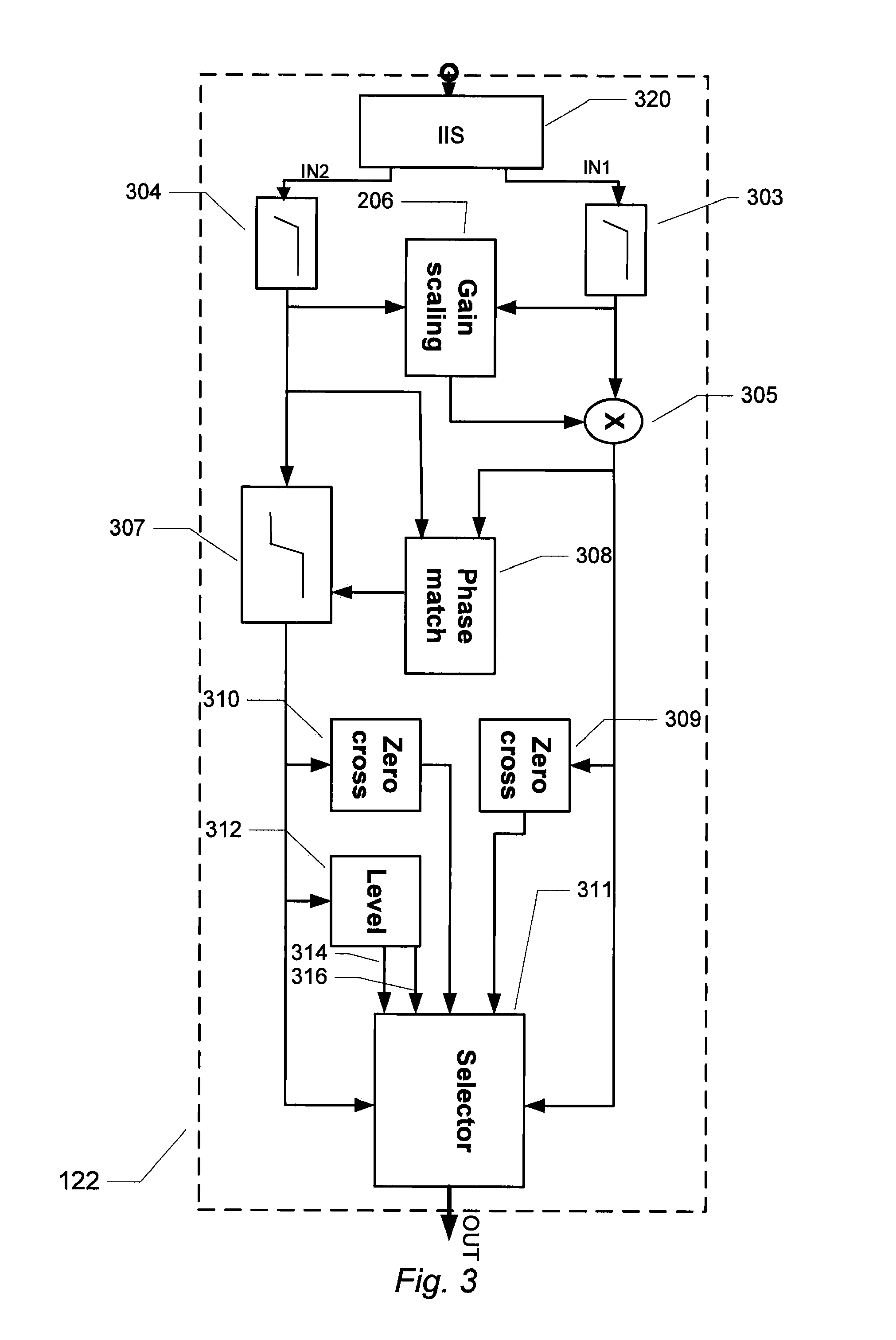
[0016]In accordance with the invention, the audio signal controller is adapted to switching from conveying or transmitting the first digital audio signal to conveying or transmitting the second digital audio signal to the controller output, or vice versa, at a zero-crossing of the first digital audio signal or the second digital audio signal. In a preferred embodiment, the switching between the first and second digital audio signals is exclusively effected at a substantially simultaneous zero-crossing of the first and second digital audio signals. By effecting the signal switching at a zero-crossing of the first and / or the second digital audio signal generation of audible artifacts such as “clicks”, “pops” or other objectionable sound artifacts in connection therewith may be eliminated or at least considerably suppressed. Switching at the zero-crossings of the first and / or the second digital audio signal(s) minimizes error energy in a waveform shape of an outgoing digital audio signal at the controller output by suppressing waveform discontinuities at a signal switch point.
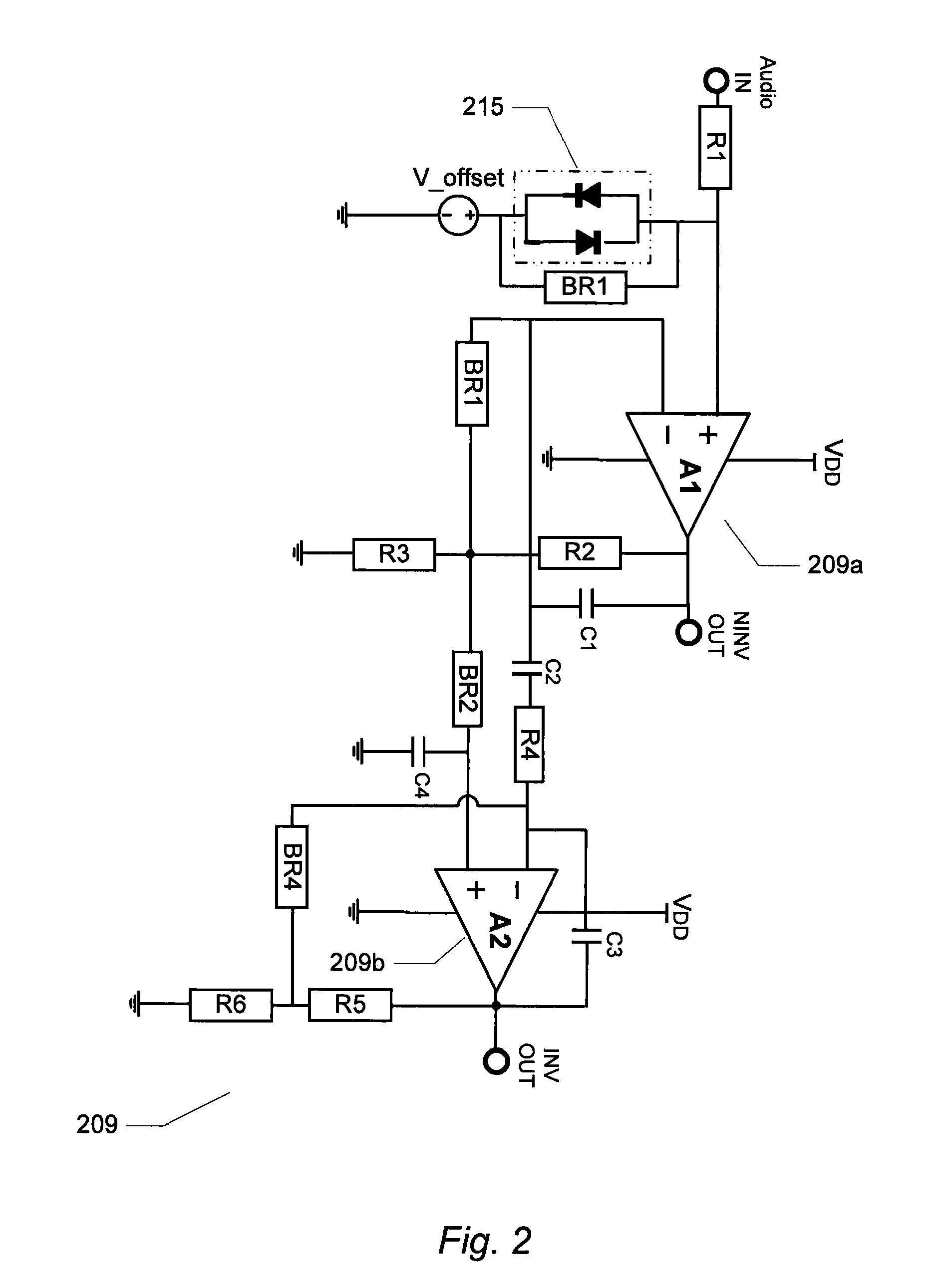
[0092]In other embodiments, the feedback network is configured to provide a lowpass transfer function from the output of the differential amplifier to the inverting input of the differential amplifier. Consequently, a high-pass small signal transfer function which is useful for attenuating low-frequency noise in the audio input signal and for suppression of effects of DC offsets at the input of the first or second preamplifier is provided.

Problems solved by technology

At this limit preamplifier non-linearity and / or analogue-to-digital converter saturation has limited further increase of the output signal of the microphone.

Method used


Image

  • Audio signal controller
  • Audio signal controller
  • Audio signal controller

Examples


Embodiment Construction

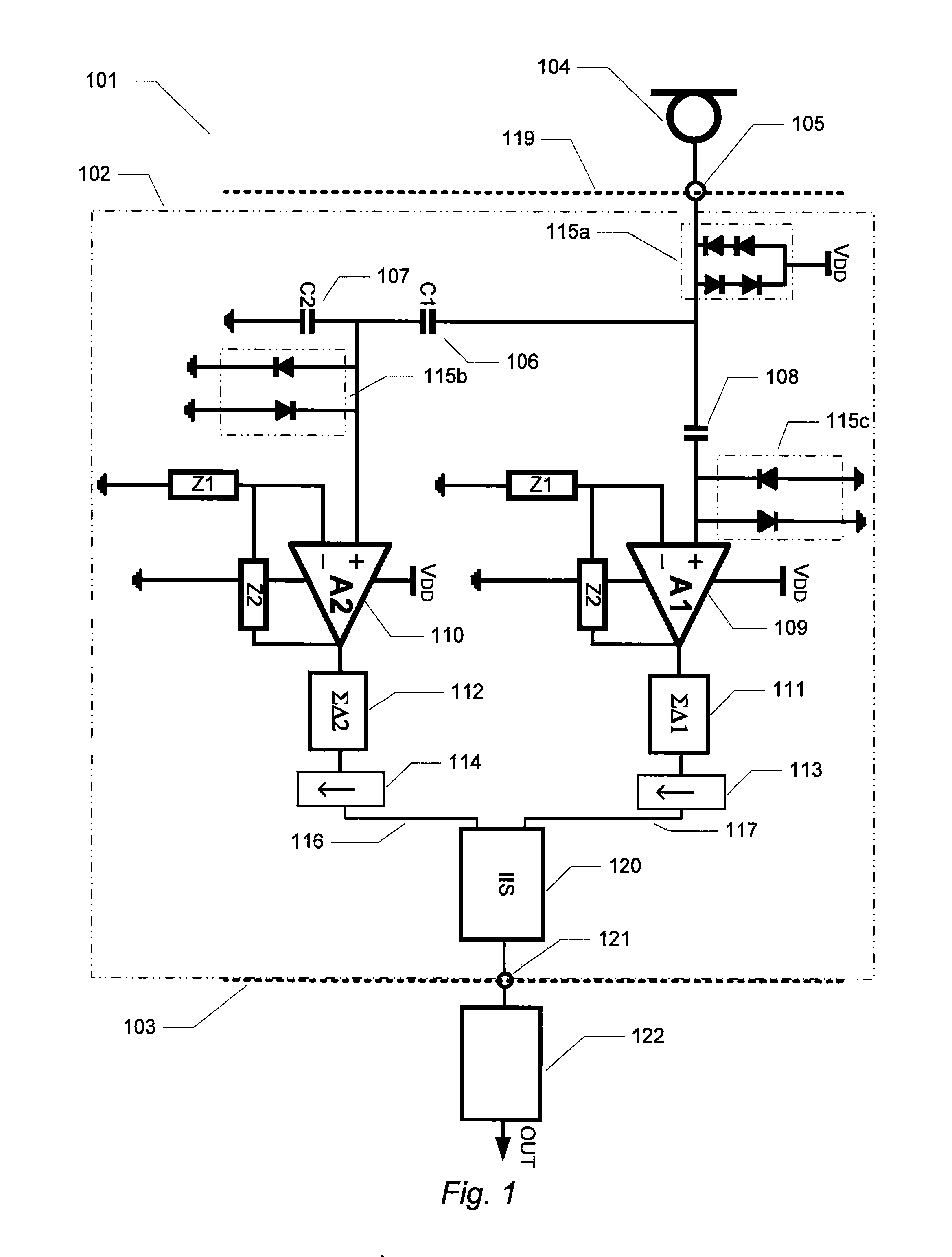
[0116]Preferred embodiments of the invention will be described and discussed in the following passages. The present embodiment of the invention will be described in connection with an associated audio amplification circuit which generates first and second digital audio signals that are applied to and processed by the inventive audio signal controller. However, the skilled person will understand that the present audio signal controller may receive and process first and second digital audio signals provided by other types of digital audio signal sources.

[0117]To assist comparisons between the different figures corresponding or identical features have been indicated by similar reference numerals on the drawings.

[0118]FIG. 1 is a schematic drawing of an audio amplification system 101 which comprises two separate circuit portions in form of an audio amplification circuit 102 serving as a front-end and an audio signal controller or selection circuit 122 serving as a back-end of the audio ...


PUM


Abstract

The present invention relates to an audio signal controller adapted to receiving first and second digital audio signals and estimating a signal feature of the first or second digital audio signal. The estimated signal feature is compared with a predetermined feature criterion and the audio signal controller switches from conveying the first digital audio signal to conveying the second digital audio signal to a controller output, or vice versa, at a zero-crossing of the first digital audio signal or the second digital audio signal based on the comparison between the estimated signal feature and the predetermined feature criterion.

Description

[0001]The present invention relates to an audio signal controller adapted to receiving first and second digital audio signals and estimating a signal feature of the first or second digital audio signal. The estimated signal feature is compared with a predetermined feature criterion and the audio signal controller switches from conveying the first digital audio signal to conveying the second digital audio signal to a controller output, or vice versa, at a zero-crossing of the first digital audio signal or the second digital audio signal based on the comparison between the estimated signal feature and the predetermined feature criterion.BACKGROUND OF THE INVENTION[0002]Acceptable handling of audio signals with very large dynamic range presents significant challenges to audio amplification and processing circuits and systems, in particular for audio amplification and processing circuits targeted for operation in portable devices and applications such as mobile terminals, hearing instru...

Claims


Application Information

Patent Timeline
Patent Type & Authority Applications(United States)
IPC IPC(8): G06F17/00
CPCH03F3/187H04S2400/13H03F3/68H03F2200/03H03F2200/331H03F2203/45138H03F2203/45552H03F2203/45571H03F2203/45586H03G1/0088H04R3/005H04R2420/01H04R2430/01H04S1/007H03F3/45475
Inventor THOMSEN, HENRIKHENRIKSEN, JENS JORGEN GAARDEFURST, CLAUS
Owner INVENSENSE
Learn More