Nozzle position correcting method for electronic device mounting apparatus

A technology of electronic devices and assembly devices, which is applied in the field of nozzle positioning correction, can solve problems such as direction changes, nozzle positioning errors, and photographic position errors are not close to each other, and achieve the effect of accurate positioning

Inactive Publication Date: 2009-07-01
JUKI CORP
View PDF6 Cites 2 Cited by
  • Summary
  • Abstract
  • Description
  • Claims
  • Application Information

AI Technical Summary

Problems solved by technology

[0005] However, when the camera mounted on the assembly head is separated from the nozzle on the X-Y plane, when the assembly head moves, for example, deflection occurs on the guide rail supporting the assembly head, thus resulting in the state of the camera and the nozzle (posture), the direction changes, and the positioning error of the nozzle does not approach the shooting position error due to the increase of the change.

Method used


Image

  • Nozzle position correcting method for electronic device mounting apparatus
  • Nozzle position correcting method for electronic device mounting apparatus
  • Nozzle position correcting method for electronic device mounting apparatus

Examples


Embodiment Construction

[0054] (overall structure of the embodiment)

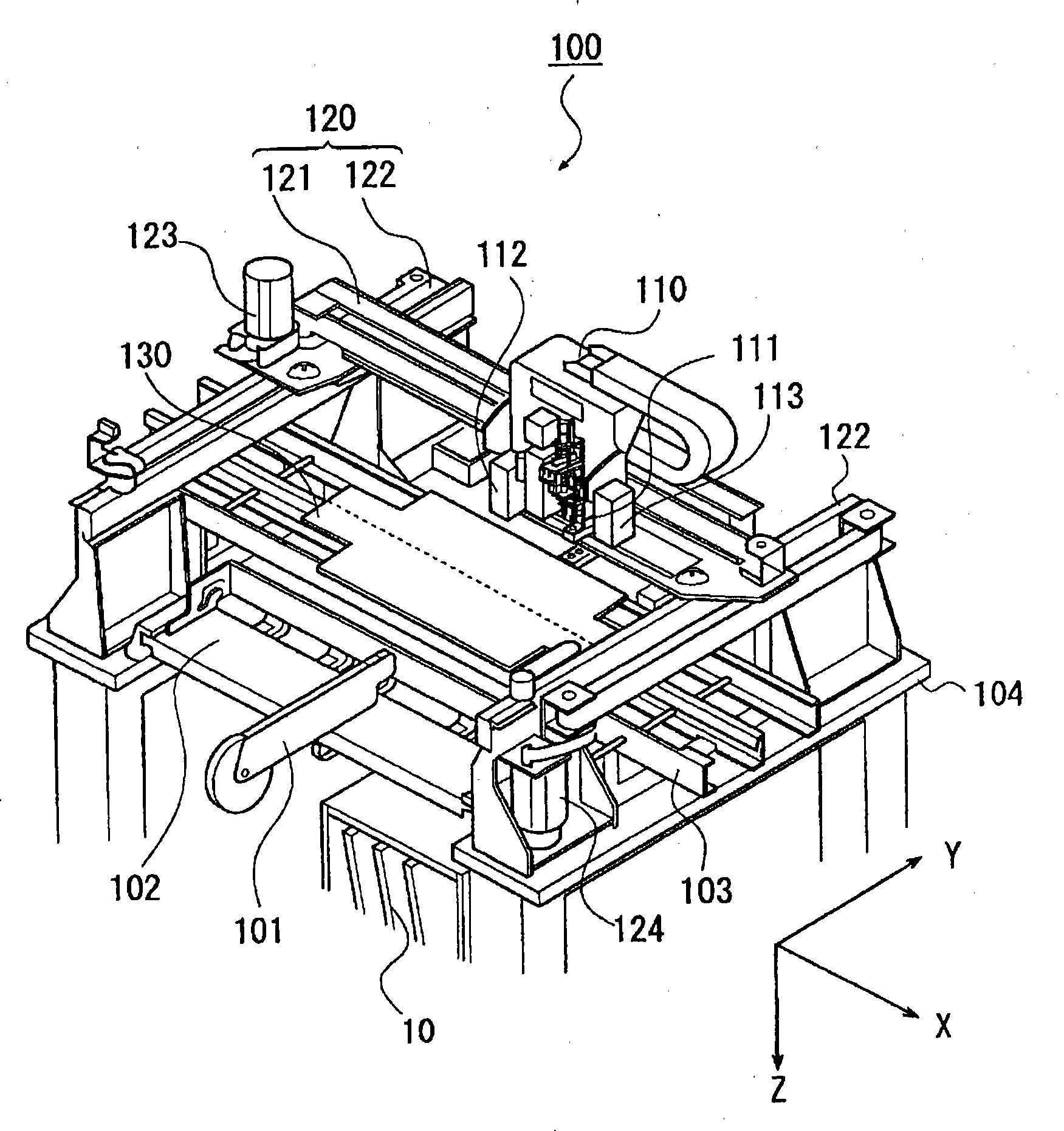
[0055] For the embodiment of the present invention, according to Figure 1 to Figure 14 Be explained. figure 1 It is a perspective view of the electronic component mounting apparatus 100 of this embodiment.

[0056] The electronic device mounting apparatus 100 is an apparatus for mounting various electronic devices on a substrate. Such as figure 1 As shown, there are: a base 104, which supports the various components described later; a plurality of electronic device feeders 101 (in figure 1 Only one is shown in the figure, in fact, there are multiple arranged along the X-axis direction described later), which supplies the electronic devices to be assembled; the feeder workbench (bank) 102, which is used to arrange and hold multiple Electronic device feeder 101; substrate conveying device 103, which conveys the substrate along a certain direction; on the way of the substrate conveying path of the substrate conveying device 103,...


PUM


Abstract

A nozzle position correction method of an electronic device assembly device can position the nozzle with higher precision. The electronic device assembly device has: a base; an assembly head with an adsorption nozzle; an X-axis guide rail guiding the assembly head along the X-axis direction; a Y-axis guide rail guiding the X-axis guide rail along the Y-axis direction; displaying a plurality of identification marks M1-Mn Marker display section; first and second cameras provided on the assembly head. This nozzle position correction method includes: a photographing process of photographing each identification mark with two cameras; a deviation amount acquisition process of obtaining the photographed position deviation amount for each camera; A Y-axis deviation determination process to calculate the deviation in the Y-axis direction from the imaging position deviation in the axial direction and the relative positional relationship between each camera and the nozzle; a positioning process to position the nozzle by correcting the calculated deviation.

Description

technical field [0001] The invention relates to a method for correcting nozzle positioning of an electronic device assembly device which moves an assembly head for electronic device assembly along a guide rail. Background technique [0002] In the existing electronic device assembly device, the electronic device is assembled on the substrate through the assembly head equipped with the nozzle for adsorption of the electronic device, and the X-Y moving mechanism that can position the assembly head at any position on the X-Y plane . Due to various reasons (for example, processing accuracy of the device, assembly accuracy, thermal expansion, etc.), sometimes there will be an error in the assembly position relative to the coordinates of the target position. [0003] In order to correct such an error, such a prior art has been disclosed (for example, refer to Patent Document 1), in which reference marks with known position coordinates are distributed on the surface of a measuring...

Claims


Application Information

Patent Timeline
Patent Type & Authority Patents(China)
IPC IPC(8): H05K13/04G01B11/00
Inventor 东盛夫桥口桃枝
Owner JUKI CORP
Why Eureka
Try Eureka