Flow regulating control system

A control system and flow regulation technology, applied in the direction of flow control using electric devices, flow control of auxiliary non-electric power, etc., can solve the problems of high power consumption, long life, difficult to provide power, etc., to achieve accurate opening size, Use the full effect of security, safety mechanisms and control mechanisms

Inactive Publication Date: 2009-07-08
黄依华
View PDF5 Cites 1 Cited by
  • Summary
  • Abstract
  • Description
  • Claims
  • Application Information

AI Technical Summary

Problems solved by technology

[0002] Traditional mechanical flow control methods generally use linear sensors or position sensors equivalent to variable resistors to adjust and feed back position signals. Such linear sensors often suffer from wear and tear in use, short lifespan, and complicated control systems. and other defects, and it is not easy to correctly control the flow regulating valve with two outlets at the same time
[0003] In the method disclosed above about the existing mechanical flow regulating device, although a stepping motor can be used as the driving component of the flow regulating device, the power consumption is relatively high due to the high driving current and operating voltage required by the stepping motor. Large, for control devices that use dry batteries as the source of power, such as: gas water heaters, gas furnaces, etc., the operation of the flow regulating valve in the burner and the power source for its ignition and control system operation often have certain limitations in implementation. Difficulty, it is difficult to provide additional power to drive the stepping motor, especially when a large amount of electronic equipment is already installed in the combustion appliance, the problem of power consumption is often caused by the implementation of the existing mechanical flow adjustment device The biggest problem facing

Method used


Image

  • Flow regulating control system
  • Flow regulating control system
  • Flow regulating control system

Examples


Embodiment Construction

[0049] According to the technical means of the present invention, the modes suitable for the implementation of the present invention are listed below, and are described as follows in conjunction with the drawings:

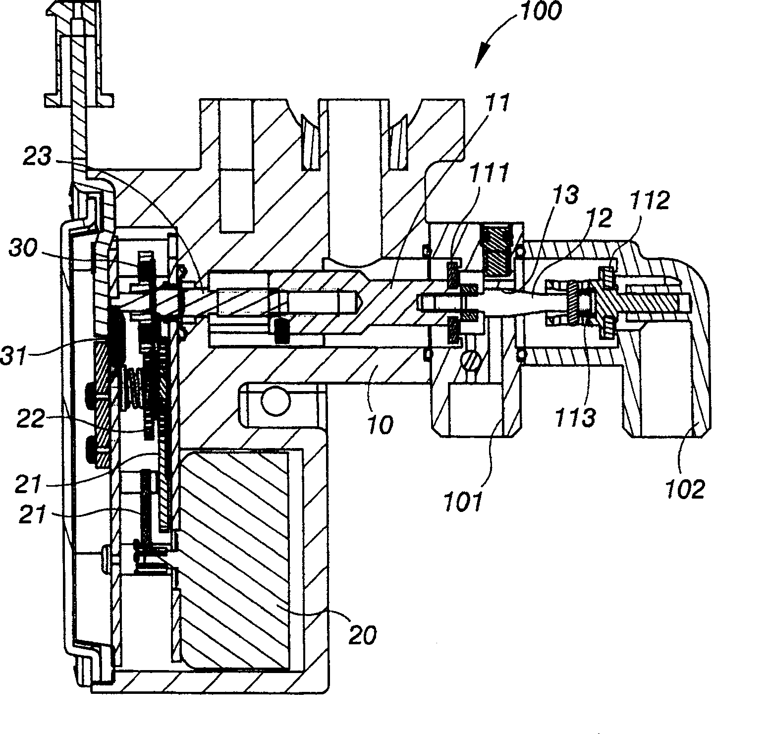
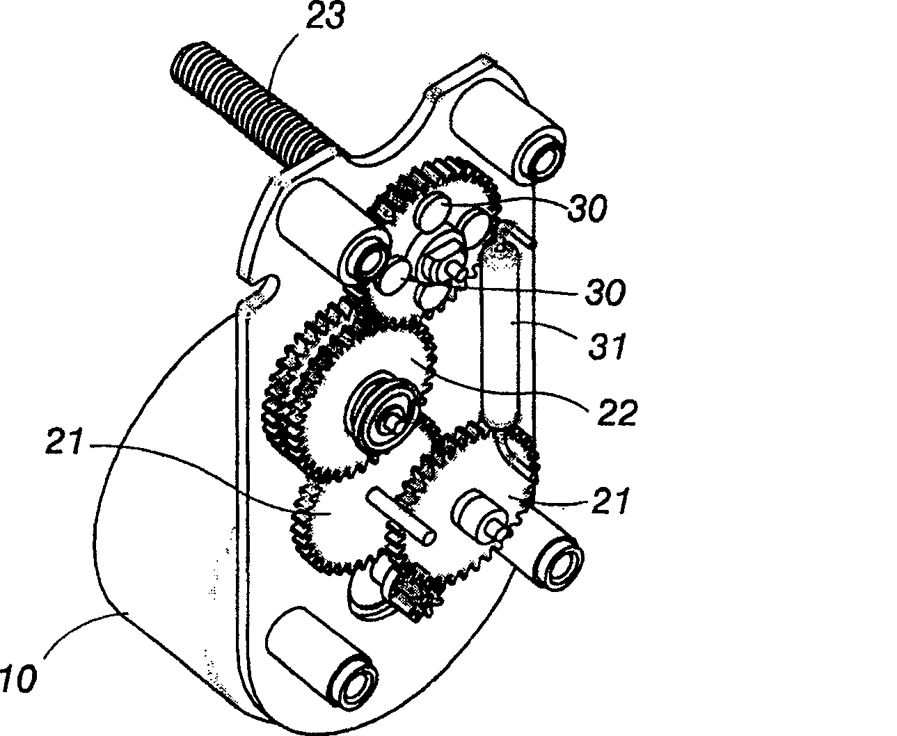
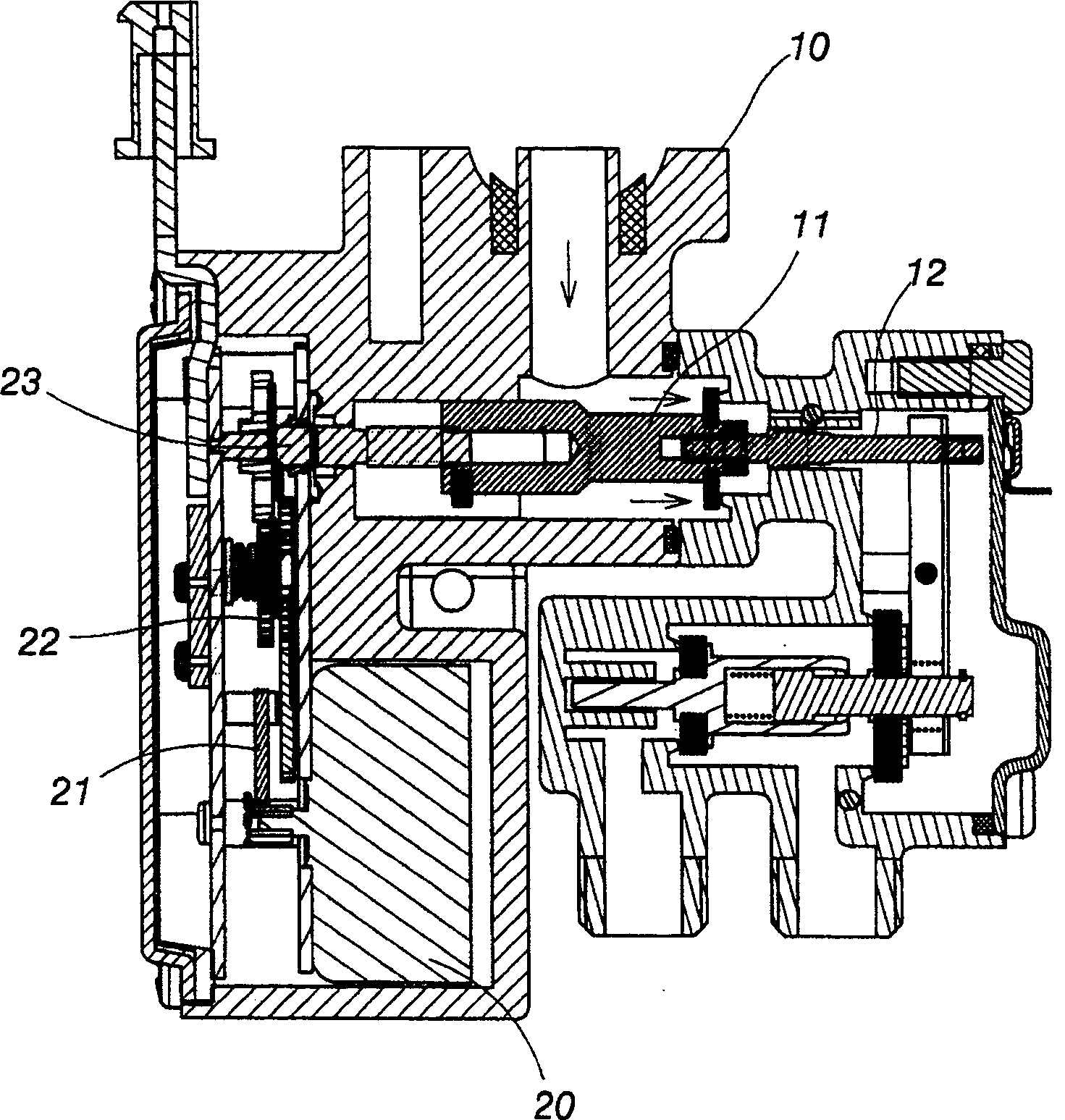
[0050] Please also see figure 1 and figure 2 shown, where figure 1 It is a sectional view of an embodiment of the present invention, figure 2 It is a schematic diagram of the motor transmission structure of the embodiment of the present invention, which reveals that the flow regulating valve control system acts on a flow regulating mechanism 100, so that the opening of the flow regulating valve 10 set in the flow regulating mechanism 100 can be adjusted accordingly. The change reaches the traffic regulator.

[0051] The flow regulating valve control system uses the rotation of the motor 20 as the driving force for the opening of the flow regulating mechanism 100. The rotation of the motor passes through several speed change gears 21 and clutch gear 22 to the t...


PUM


Abstract

The flow regulating valve control system of the present invention acts on a flow regulating mechanism, the opening of the flow regulating valve set in the flow regulating mechanism changes to achieve flow regulation, and the rotation of the motor is used as the opening of the flow regulating valve. Power, the power of the motor is transmitted to the terminal output shaft through several speed change gears and clutch gears, and the terminal output shaft is used to drive the opening of the flow regulating valve to change; through the magnet that rotates synchronously with the terminal output shaft and the aforementioned magnet The corresponding magnetic induction component calculates the number of revolutions of the terminal output shaft to obtain different feedback signals to know the opening of the flow regulating valve; when the terminal output shaft can no longer rotate at the maximum and minimum opening of the flow regulating valve, the clutch gear will generate The action of protection disengagement makes it impossible for the magnetic induction component to detect the feedback signal. Referring to the positive and negative rotation of the motor, it is known that the opening of the flow regulating valve is the maximum or minimum, which is used as a reference method for zeroing the frequency signal of the flow regulating valve control system.

Description

technical field [0001] The present invention is a flow adjustment control system, especially a system applied to burners to adjust and control the flow of gas, and can even adjust the flow of gas to burners with double fire rows to adjust the firepower of the burners. Give precise control. Background technique [0002] Traditional mechanical flow control methods generally use linear sensors or position sensors equivalent to variable resistors to adjust and feed back position signals. Such linear sensors often suffer from wear and tear in use, short lifespan, and complicated control systems. and other defects, and it is not easy to correctly control the flow regulating valve with two outlets at the same time. [0003] In the method disclosed above about the existing mechanical flow regulating device, although a stepping motor can be used as the driving component of the flow regulating device, the power consumption is relatively high due to the high driving current and operat...

Claims


Application Information

Patent Timeline
Patent Type & Authority Patents(China)
IPC IPC(8): G05D7/03G05D7/06
Inventor 黄依华
Owner 黄依华
Why Eureka
Try Eureka