
Optical catalytic hydrogen production system by directly utilizing solar energy to decompose water

A hydrogen production system and solar energy technology, applied in the directions of hydrogen production, energy input, etc., can solve problems such as the inability to directly and effectively utilize solar energy, and achieve the effects of simple structure, strong adaptability and low cost.

Active Publication Date: 2009-07-22
XI AN JIAOTONG UNIV
View PDF3 Cites 2 Cited by
  • Summary
  • Abstract
  • Description
  • Claims
  • Application Information

AI Technical Summary

Problems solved by technology

[0004] Retrieval, review of relevant literature, patents and other materials found that there are currently many reports on photocatalytic hydrogen production reactions, but due to limitations in experimental equipment and other conditions, most of these systems use xenon lamps, tungsten lamps and other simulated solar light sources for experiments, and cannot directly Effective use of solar energy
In the field of photocatalysis, the application of solar energy is mainly limited to photocatalytic degradation of organic matter, but there is no official report on the direct use of solar energy to photocatalytically split water to produce hydrogen.

Method used


Image

  • Optical catalytic hydrogen production system by directly utilizing solar energy to decompose water
  • Optical catalytic hydrogen production system by directly utilizing solar energy to decompose water
  • Optical catalytic hydrogen production system by directly utilizing solar energy to decompose water

Examples


Embodiment Construction

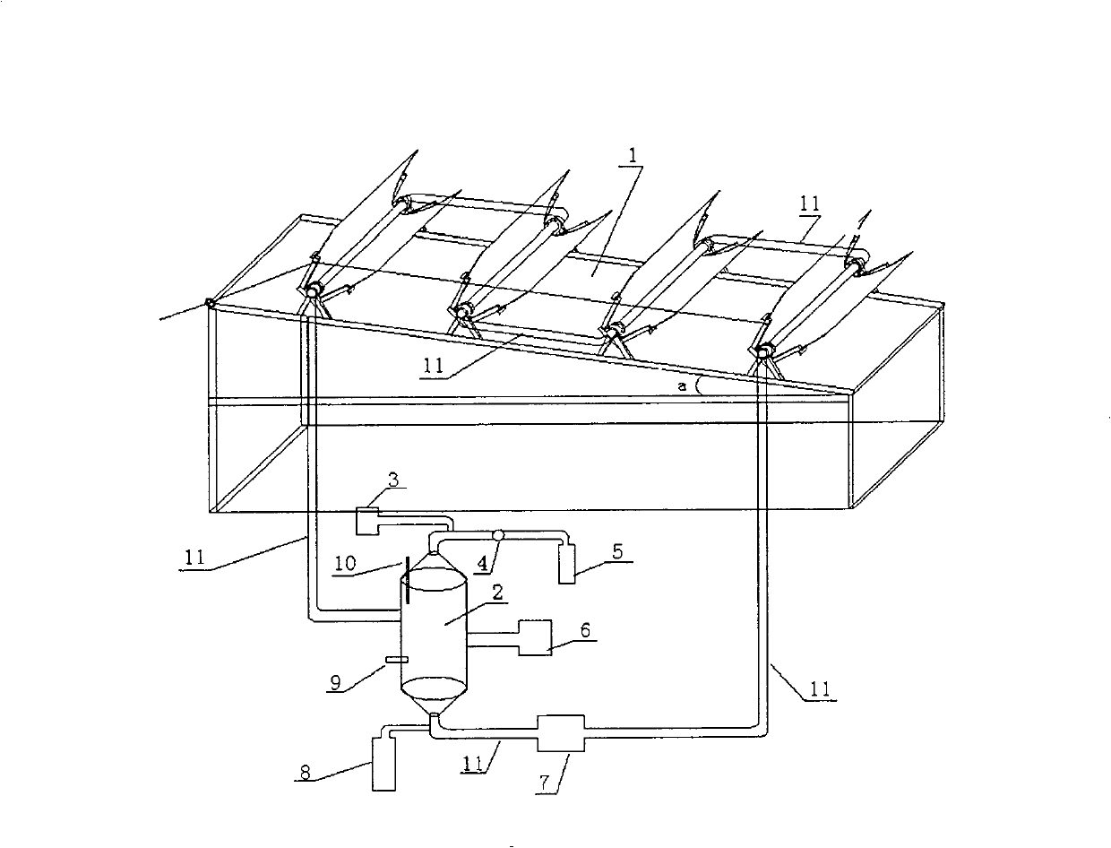
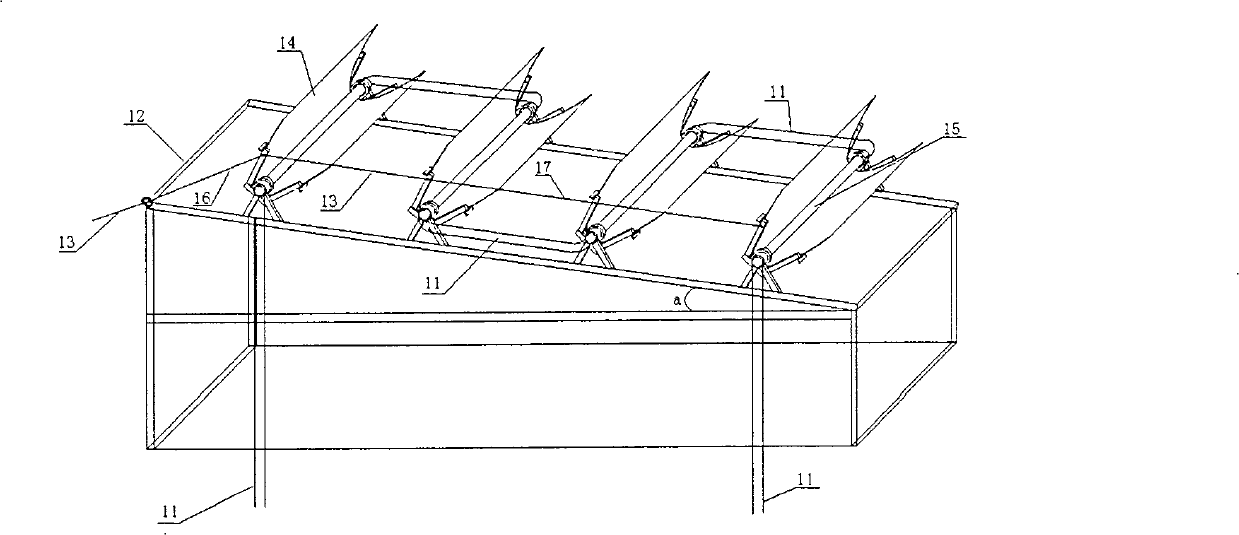
[0023] Such as figure 1 As shown, the feed port of the liquid storage tank 2 is connected with a feed pump 6, and the top outlet of the liquid storage tank 2 is connected to the gas chromatograph 3, the flow meter 4 and the gas collecting bottle 5 in turn; the bottom outlet is connected to the circulation pump 7, and the circulation pump 7 is connected to one end of the photocatalytic reactor 1, and the other end of the photocatalytic reactor 1 is connected to the liquid storage tank 2; a temperature probe 9 and a precision pressure gauge 10 are arranged on the wall of the liquid storage tank 2. The above components are connected by vacuum glass valves, PVC pipes 11 and silicone tubes to form the reaction part, circulation part, monitoring part and feeding and discharging parts of the device.

[0024] Reaction part: composed of photocatalytic reactor 1, the photocatalytic reaction is carried out in the tubular reactor 15, when the reaction liquid flows through the tubular reac...


PUM

PropertyMeasurementUnit
lengthaaaaaaaaaa

Abstract

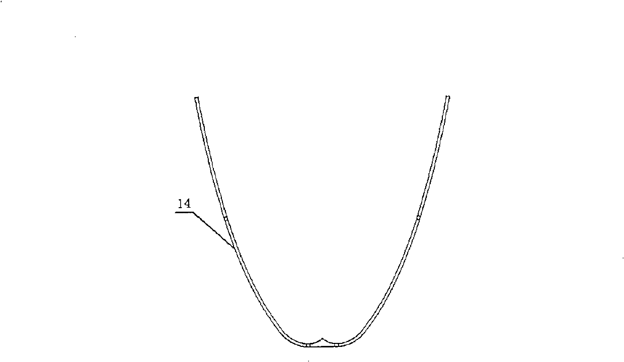
This invention discloses a system for utilizing solar energy to catalyze and analyze water to produce hydrogen directly, in which, a gas chromatograph, a flowmeter and a gas collecting bottle are connected orderly on the exit of the top of a liquid tank, a circulation pump is connected at the bottom, one end of a light-catalyzed reactor is connected to the pump and the other end is connected to the liquid tank set with a temperature probe and a precision pressure meter on the wall, in which, the included angle of the slant and the level of the stainless steel frame is a, which is the latitude at the spot, at least one compound paraboloid optical collector is set on the slant fixed by a bearing, the collectors are connected by screws, and a pipe reactor is set at the center of each of the collectors and serial together by PVC tubes.

Description

technical field [0001] The invention belongs to the field of large-scale preparation of renewable energy, and relates to a device for producing hydrogen by photocatalytically decomposing water under direct solar light and a hydrogen separation and collection device, in particular to a system for producing hydrogen by directly utilizing solar photocatalytically decomposing water. Background technique [0002] Insufficient supply of conventional primary energy, severe pollution caused by the use of fossil energy, and energy problems in rural and remote areas have put my country under multiple pressures, prompting people to look for new clean alternative energy. Hydrogen is odorless and non-toxic, and the product after combustion is water and non-polluting. It is convenient to store and transport, and easy to regenerate. It has been generally regarded as the most ideal pollution-free green energy in the new century. At present, the international community has been vigorously pr...

Claims


Application Information

Patent Timeline
Patent Type & Authority Patents(China)
IPC IPC(8): C01B3/06
CPCY02E60/36Y02P20/133
Inventor 郭烈锦敬登伟张相辉邢婵娟张西民
Owner XI AN JIAOTONG UNIV
Learn More