Power-supply device for discharge lamp

一种供电装置、放电灯的技术,应用在气体放电灯的使用、照明装置、电光源等方向,能够解决灯寿命缩短等问题

Inactive Publication Date: 2009-07-22
USHIO DENKI KK
View PDF10 Cites 0 Cited by
  • Summary
  • Abstract
  • Description
  • Claims
  • Application Information

AI Technical Summary

Problems solved by technology

[0019] The purpose of the present invention is to solve the problems existing in the background technology, that is, the problem that the life of the lamp is shortened when the arc discharge of the high-intensity discharge lamp is switched.

Method used


Image

  • Power-supply device for discharge lamp
  • Power-supply device for discharge lamp
  • Power-supply device for discharge lamp

Examples


Embodiment Construction

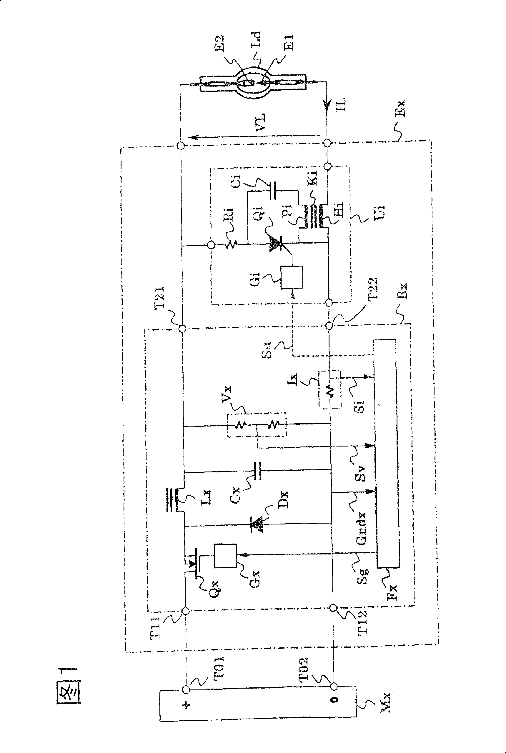
[0056] First, a first embodiment of the invention according to claim 1 of the present invention will be described. FIG. 5 shows a simplified configuration of the power supply control circuit Fx. The above-mentioned lamp voltage signal Sv is input to the AD converter Adc in the integrated control unit Xpu, converted into digital lamp voltage data Sxv having an appropriate number of digits, and input to the microprocessor device Mpu.

[0057] Here, the microprocessor device Mpu includes a cpu, a program memory, a data memory, a clock pulse generating circuit, a time counter, an IO controller for inputting and inputting data signals, and the like.

[0058] The microprocessor unit Mpu generates clipping capability control target data Sxt for the clipping capability control circuit Ud described below based on the calculation referring to the above-mentioned lamp voltage data Sxv and condition judgment corresponding to the system state at that time. The aforementioned clipping capa...


PUM


Abstract

The object of the present invention is to provide a power feeding apparatus to solve the problem that the life time of the lamp is shortened when the discharge status changes to arc discharge. The solution means to solve the above problem is: the power feeding apparatus controls the current flowing in the discharge lamp not to exceed a current limit value. Until the discharge status changes to the arc discharge, the current limit value is a first current limit value, and after that, the current limit value changes to the second current limit value. The first current limit value is less than 70% of the second current limit value. Furthermore, the first current limit value is maintained for more than 0.2 ms after the discharge status changes to the arc discharge.

Description

technical field [0001] The present invention relates to a discharge lamp power supply device for lighting high-intensity discharge lamps (HID lamps) such as high-pressure mercury discharge lamps and metal halide lamps, which are used as light sources for optical devices such as projectors, for example. Background technique [0002] In light source devices for optical devices such as liquid crystal projectors and DLP(TM) (Texas Instruments) projectors, a high-intensity discharge lamp and a power supply device for lighting are used in combination. [0003] There are two types of drive for the discharge lamp: one is the electrode polarity of the two poles of the discharge lamp, that is, one is the cathode and the other is the anode, and the relationship is constant; the other is the cathode and the anode. An AC drive whose relationship alternates substantially periodically. And, in AC driving, the speed of this polarity change, that is, the driving frequency may be driven at a...

Claims


Application Information

Patent Timeline
Patent Type & Authority Patents(China)
IPC IPC(8): H05B41/28H05B41/24H05B41/282H05B41/292H05B41/38
CPCY02B20/208H05B41/2928H05B41/388Y02B20/00
Inventor 冈本昌士福田稔竹清敦
Owner USHIO DENKI KK
Why Eureka
Try Eureka