Windshield wiping device for a motor vehicle

A technology for car windows and cars, applied in the field of car window wiper devices, to achieve the effect of improving safety

Inactive Publication Date: 2009-07-29
ROBERT BOSCH GMBH
View PDF6 Cites 0 Cited by
  • Summary
  • Abstract
  • Description
  • Claims
  • Application Information

AI Technical Summary

Problems solved by technology

Although the aim is to achieve a break between the support element and the profile tube or between the butt end and the profile tube, this proposal has the disadvantage that there is a lot of material especially in the region where the support element and the butt end are connected to the profile tube

Method used


Image

  • Windshield wiping device for a motor vehicle
  • Windshield wiping device for a motor vehicle

Examples


Embodiment Construction

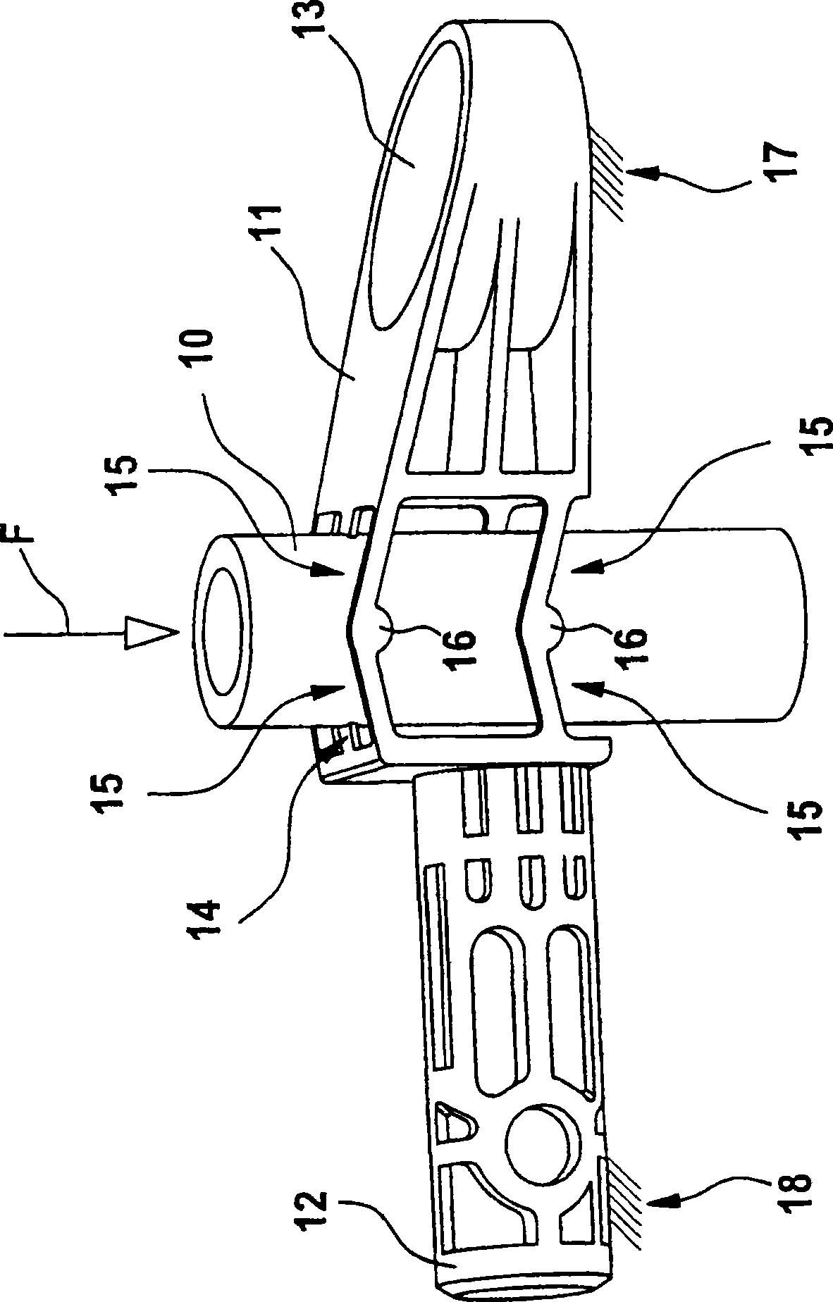
[0018] figure 1 A forming tube 10 is shown. A drive shaft, not shown in detail here, for driving a wiper arm, likewise not shown in detail here, can be inserted into the profile tube. A support element 11 and a butt end 12 are connected to the profile tube 10 . The carrier element 11 has a receiving opening 13 . Fastening means (not shown here) for fastening the carrier element 11 to a body (not shown here) can be inserted into the receiving opening. A solid fastening point 17 is formed by the connection of the support element 11 to the vehicle body. A sheet metal tube, also not shown, can be crimped (ancrimbar) onto the butt end 12 so that the butt end 12 has a firm fastening point 18 . The support element 11 and the butt end 12 are connected to the profile tube 10 via webs 14 and 15 . The strips 15 each have an elbow 16 which is connected to the profile tube 10 . When a force F, such as a collision force when hitting a pedestrian, acts on the profiled tube 10, the prof...


PUM


Abstract

Windshield wiper device for motor vehicles, the wiper device has at least one profiled tube (10) for accommodating a transmission shaft for driving at least one wiper arm, wherein the at least one profiled tube (10) can be combined with a The supporting element (11) which can be connected to the vehicle body and is connected to a butt end (12) which accommodates a thin sheet tube, and in order to connect the at least one profiled tube (10) to the supporting element (11) and / or to the butt end (12) connection and connection strips (14, 15) are provided.

Description

technical field [0001] The invention relates to a windshield wiper device for a motor vehicle, which has at least one profiled tube for receiving a transmission shaft for driving at least one wiper arm, wherein at least one profiled tube can be combined with A support member attachable to the body, and a butt end connection receiving a sheet tube. Background technique [0002] Pedestrians are completely unprotected in a collision with a car. Especially inflexible hard parts under the bonnet often cause serious injuries when pedestrians hit the motor vehicle. The windshield wipers are located in areas where pedestrians are often hit by vehicles. In order to minimize this risk of injury, car manufacturers are required to set the minimum distance between the hood and the wiper drive to be 65 mm to 85 mm. But the drive shaft of the windshield wiper usually protrudes from the molded tube, and usually the distance from it to the bonnet is only 10 mm. When a pedestrian's head h...

Claims


Application Information

Patent Timeline
Patent Type & Authority Patents(China)
IPC IPC(8): B60S1/04B60S1/34
CPCB60S1/0425Y10T403/11B60S1/34B60S1/0488F16B2200/63B60S1/04B60S1/32
Inventor A·克劳斯J·迪特里希
Owner ROBERT BOSCH GMBH
Why Eureka
Try Eureka