
Electrical household food processor with simplified control

A technology for household and electrical appliances, which is applied in the field of household cooking and processing electrical appliances, which can solve the problems of expensive devices and achieve the effect of simplified manufacturing

Active Publication Date: 2009-08-12
SEB SA
View PDF2 Cites 2 Cited by
  • Summary
  • Abstract
  • Description
  • Claims
  • Application Information

AI Technical Summary

Problems solved by technology

The proposed device is relatively expensive

Method used


Image

  • Electrical household food processor with simplified control
  • Electrical household food processor with simplified control
  • Electrical household food processor with simplified control

Examples


Embodiment Construction

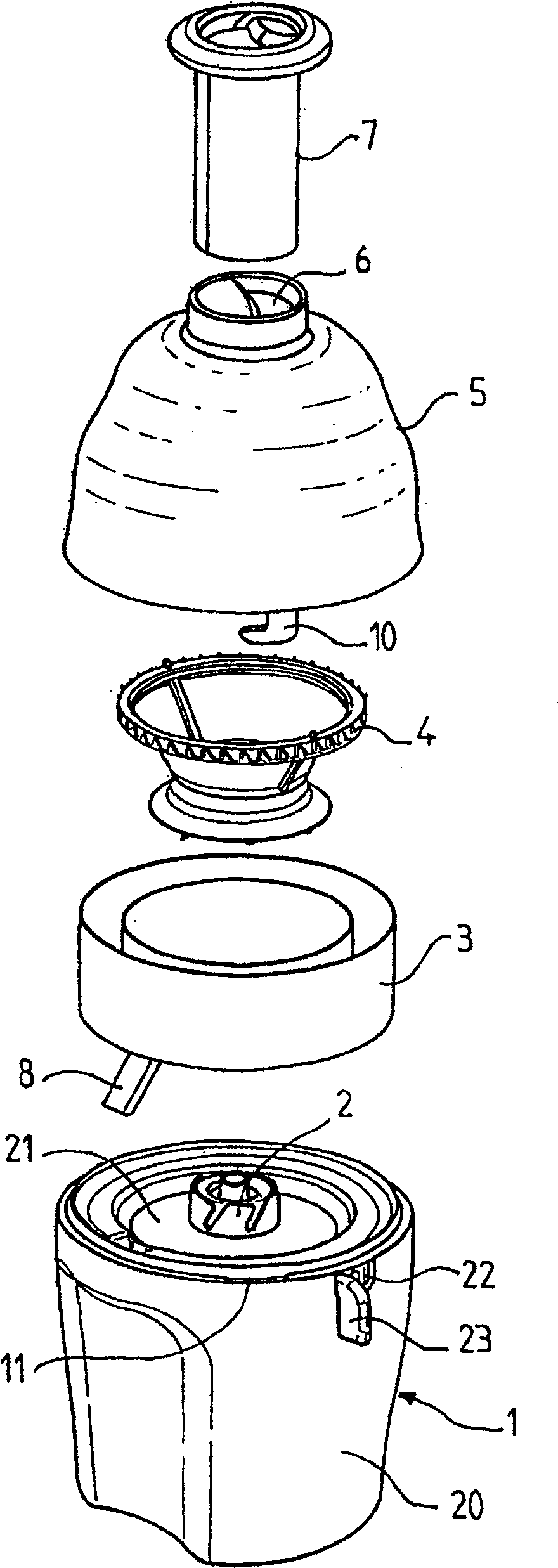
[0031] [31] figure 1 A centrifuge forming the household cooking and processing appliance of the present invention is shown. The household cooking and processing appliance includes a housing 1 containing a motor, a container 3 , a rotary tool 4 formed by a filter bucket and a cover 5 . The cover 5 has an opening 6 into which a tappet 7 can be inserted. The container 3 has an outlet 8 for the juice obtained during preparation. A drive shaft 2 connected to a motor (not shown) is mounted on the housing 1 . The drive shaft 2 is used to drive the rotary tool 4 to rotate. The container 3 and the rotary tool 4 are detachably arranged on the housing 1 .

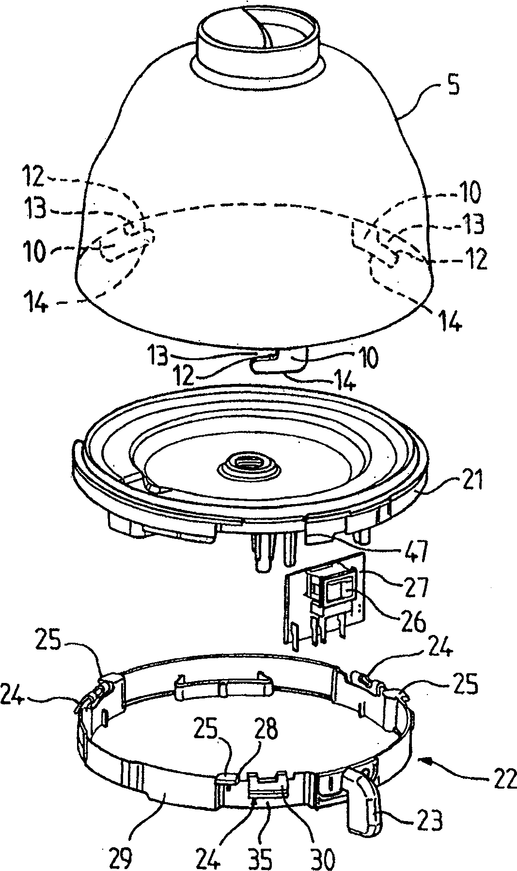
[0032] [32] The housing 1 has a main body 20 forming a housing with an upper opening. A bottom plate 21 is fitted in the upper opening. The bottom plate 21 is assembled with the main body 20 by screws, for example. To this end, the lower surface of the bottom plate 21 has a joint 45 for fixing the motor and a joint 46 for fixin...


PUM


Abstract

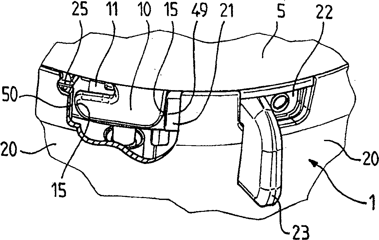
The apparatus has an activating unit (14) that deforms in a reversible manner and belongs to a control unit (22). The unit (14) separates a locking unit (24) from a stopper (47) of a casing, when a cover (5) is placed on the casing. The control unit (22) is displaced towards an apparatus operating position for engaging a retaining unit (25) with a locking unit (12) before activating a switch (26).

Description

technical field [0001] [01] The present invention relates to the technical field of household cooking and processing appliances, which has a cover covering a base that drives a rotary tool. Background technique [0002] [02] Household cooking and processing appliances of the aforementioned type include, inter alia, centrifuges and household electric small grinders. A centrifuge has a panier rotating within a hemispherical bol. The home electric mini grinder has a cutting tool that rotates in a hemispherical housing. [0003] [03] It is known that FR2730398 proposes a food preparation device comprising a housing with a movable control for operating a switch connected to a motor. The control actuates two retaining mechanisms for cooperating with the openings of the hood. A locking mechanism disposed on the housing detects the presence of the cover to actuate the control. However, the proposed control device consists of several components. The control member drives the mov...

Claims


Application Information

Patent Timeline
IPC IPC(8): A47J44/00A47J43/00A47J43/07
CPCA47J43/0772A47J43/046
Inventor A·巴索拉
Owner SEB SA
Learn More