Laminated element provided with a heated layer

A technology of multi-layer components and covering layers, applied in heating methods, electrical components, ohmic resistance heating, etc., can solve problems such as deterioration

Inactive Publication Date: 2009-08-12
SAINT-GOBAIN GLASS FRANCE
View PDF6 Cites 1 Cited by
  • Summary
  • Abstract
  • Description
  • Claims
  • Application Information

AI Technical Summary

Problems solved by technology

However, it is clearly necessary to avoid that the covering layer bonded to the covered glazing, such as the bonded panels of multi-glazed windows, deteriorates with the temperatures reached in normal operation

Method used


Image

  • Laminated element provided with a heated layer
  • Laminated element provided with a heated layer

Examples


Embodiment Construction

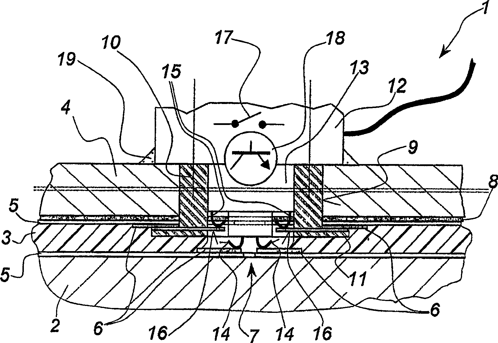
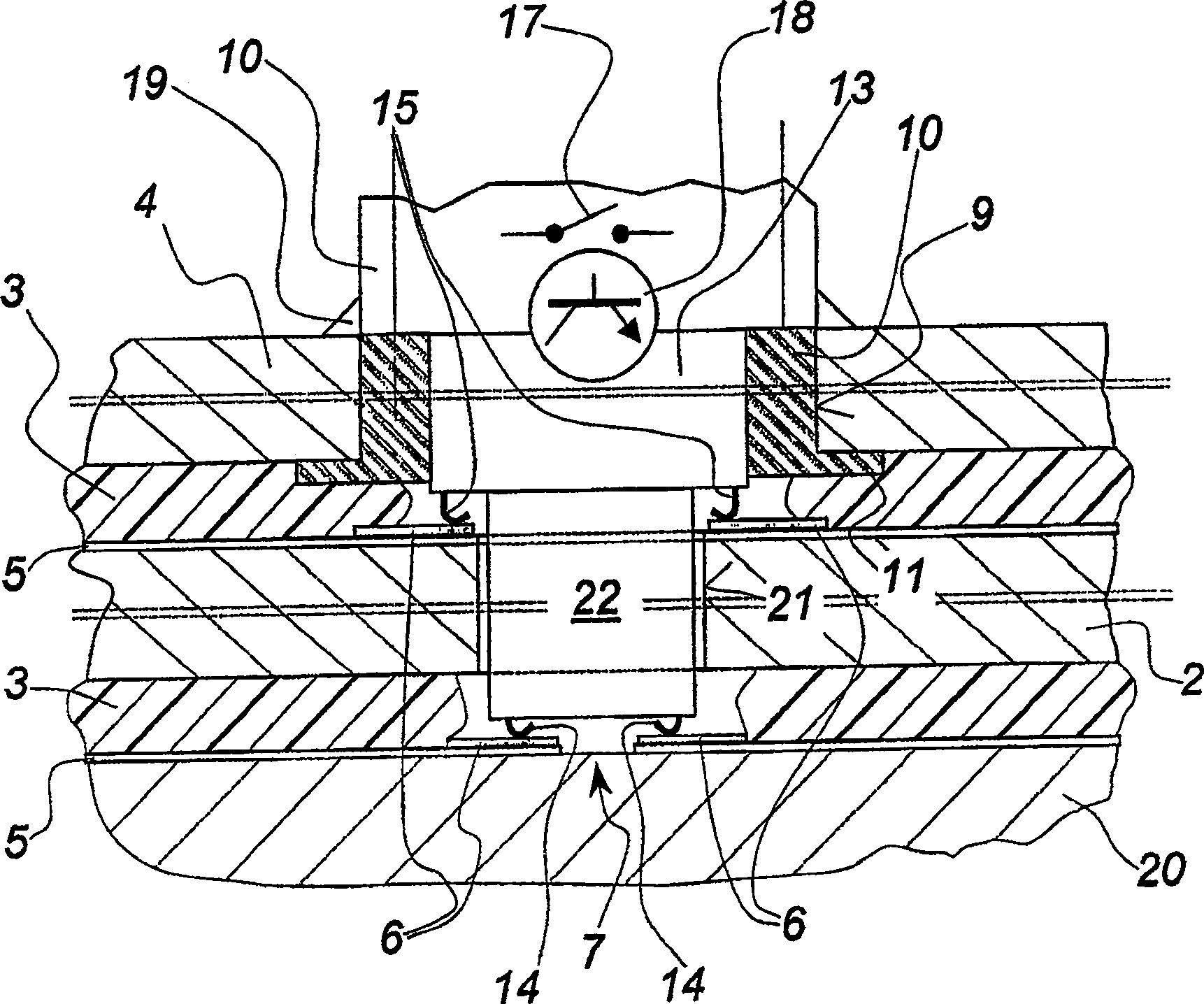
[0033] exist figure 1 Here, the plate-shaped heating element 1 according to the invention is implemented in the form of a multi-glazed window with a first rigid pane 2 , an adhesive layer 3 and a second rigid pane 4 . Said rigid panes 2 and 4 are preferably preheated or partially prestressed panes. On the flat side facing the adhesive layer 3 each pane is provided with a heating layer 5 . Only a portion of the thickness of the rigid glazing 2 is shown and the dashed double line through the rigid glazing 4 indicates that the shown thickness is shortened. It can be understood that the two rigid panes are thicker than the adhesive layer 3 .

[0034] Said heating layer 5 comprises a composition and / or a continuous layer sufficiently resistant to thermal stresses and adapted to the particular application and possibly to the prestressing of said glazing when used as a surface heating layer. Suitable layer systems are described in the prior art in a number of variants, so that the...


PUM


Abstract

The glass pane has two glass panes (2,4) glued to each other on a surface. Each pane has an electro-conductive coating (5) over the entire surface that can be heated by an electrical voltage using electrodes (6). One of the panes has a cutout part (9) in a connecting region, through which external electrical connectors (12,14,15) can be passed. The connectors are brought into contact with the two coatings.

Description

technical field [0001] The invention relates to a plate-shaped multilayer element provided with a heating layer. Background technique [0002] Such heating on glass or other non-conductive supports can be used as a heating body (by radiation) if the installed heating power meets the stated purpose. These heating elements can be installed on or in the walls of a building or added to the building, ie replace the usual (central) heating body. For this, it does not have to be implemented in the form of a window, but also in the form of a mirror, in the form of a decorative surface, etc. In general, it is also possible to use plate-like elements in order to generate heat via the surface of mechanical devices, for example domestic appliances, the small installation height of which and the very easy-to-clean smooth surface offer great advantages. [0003] The power supply of heating layers with large surfaces requires the use of relatively high voltages. Reliable electrical insu...

Claims


Application Information

Patent Timeline
Patent Type & Authority Patents(China)
IPC IPC(8): H05B3/84B32B17/10F24D13/02H01R13/24
CPCB32B17/10174H05B2203/016B32B17/10036H05B3/84B32B17/10788H01R13/2442F24D13/022B32B17/10761H01R12/714B32B17/10045Y02B30/00
Inventor D·曼
Owner SAINT-GOBAIN GLASS FRANCE
Why Eureka
Try Eureka