Apparatus for effectively compensating three-phase unbalance load and reactive power
A load-balancing, three-phase technology, applied in the direction of reactive power adjustment/elimination/compensation, reactive power compensation, multi-phase network asymmetry reduction, etc., can solve the problems of device dynamic response speed limitation, high cost, difficult to meet, etc. , to achieve the effect of increasing compensation capacity, low device cost and improving utilization rate
- Summary
- Abstract
- Description
- Claims
- Application Information
AI Technical Summary
Problems solved by technology
Method used
Image
Examples
Embodiment 1
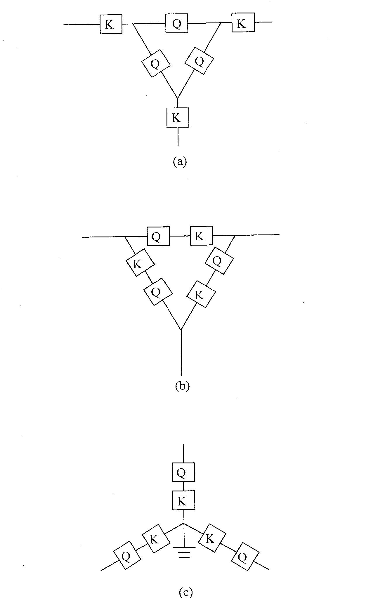
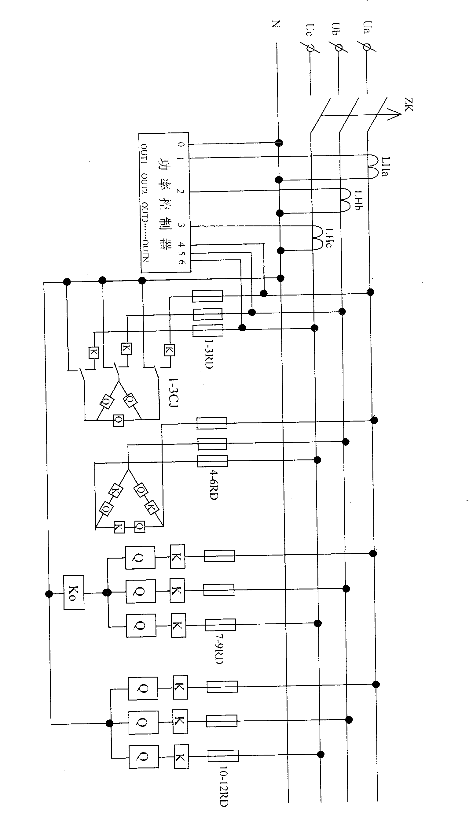
[0043] image 3 It is a schematic diagram of a more general specific embodiment of the present invention: it includes a cabinet and a main switch, three current sampling circuits, three voltage sampling circuits, a power controller, twelve fuses, A Δjx compensation unit, a Δl compensation unit, a Yxo compensation unit, a Yo compensation unit (in this example, the compensation device Q in all compensation units is a capacitor; all switches K, Ko and 1-3CJ are contacts and the voltage of its control coil is 220VAC). The current sampling is composed of three transformers LH1, LH2, and LH3 used to detect the three-phase load current, one end of which is respectively connected to the input ends 1, 2, and 3 of the power controller, and the other ends are connected together. , and then connected to the 0 terminal of the power controller. The voltage sampling circuit is a wire connected to the load power supply and the power controller respectively, one end of which is respectively ...
Embodiment 2
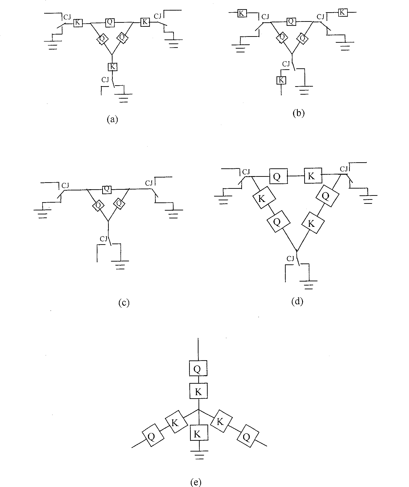
[0047] Figure 4 It is a schematic diagram of using Δxx compensation unit to transform the existing compensation device composed of Δx compensation unit: it includes a cabinet and a main switch, three current sampling circuits, three voltage sampling circuits, and a power controller are installed in the cabinet , twelve fuses, four Δx compensation units, and four Δxx compensation units. In this example, the compensation devices Q in all compensation units are capacitors; all switches CJ 1-24 There are contacts and the voltage of the control coil is 220VAC). The current sampling is composed of three transformers LH1, LH2, and LH3 used to detect the three-phase load current, one end of which is respectively connected to the input ends 1, 2, and 3 of the power controller, and the other ends are connected together. , and then connected to the 0 terminal of the power controller. The voltage sampling circuit is a wire connected to the load power supply and the power controller res...
Embodiment 3
[0049] Figure 5 It is a schematic diagram of using Δlx compensation unit to transform the existing compensation device composed of Δl compensation unit. It consists of a cabinet and a main switch, three current sampling circuits, three voltage sampling circuits, a power controller, twelve fuses, two Δl compensation units, a Yxo compensation unit, a Yo compensation unit unit (in this example all compensation devices Q in the compensation unit are capacitors; all switches K and Ko are non-contact). The current sampling is composed of three transformers LH1, LH2, and LH3 used to detect the three-phase load current, one end of which is respectively connected to the input ends 1, 2, and 3 of the power controller, and the other ends are connected together. , and then connected to the 0 terminal of the power controller. The voltage sampling circuit is a wire connected to the load power supply and the power controller respectively, one end of which is respectively connected to inpu...
PUM
 Abstract
Description
Claims
Application Information
 - R&D
- Intellectual Property
- Life Sciences
- Materials
- Tech Scout
- Unparalleled Data Quality
- Higher Quality Content
- 60% Fewer Hallucinations
Browse by: Latest US Patents, China's latest patents, Technical Efficacy Thesaurus, Application Domain, Technology Topic, Popular Technical Reports.
© 2025 PatSnap. All rights reserved.Legal|Privacy policy|Modern Slavery Act Transparency Statement|Sitemap|About US| Contact US: help@patsnap.com


