Column-type heat tube and its manufacturing method

A manufacturing method and heat pipe technology, which are applied in indirect heat exchangers, lighting and heating equipment, etc., can solve the problems affecting the large-scale application of heat pipe radiators, increase processing difficulty, increase thermal resistance, etc., and achieve light weight and fast thermal conductivity. , the effect of reducing thermal conductivity

Inactive Publication Date: 2009-09-02
嘉善华昇电子热传科技有限公司
View PDF8 Cites 1 Cited by
  • Summary
  • Abstract
  • Description
  • Claims
  • Application Information

AI Technical Summary

Problems solved by technology

[0004] Since the small heat pipes are welded together with the substrate, the heat generated by the electronic components is firstly transferred to the substrate, and then the heat is transferred from the substrate to the heat pipe, which increases the thermal resistance, and the processing difficulty of installing heat sinks on multiple small heat pipes increases, the cost is high, and the impact The large-scale application of this heat pipe radiator

Method used


Image

  • Column-type heat tube and its manufacturing method
  • Column-type heat tube and its manufacturing method
  • Column-type heat tube and its manufacturing method

Examples


Embodiment Construction

[0028] The present invention will be further described below in conjunction with accompanying drawing:

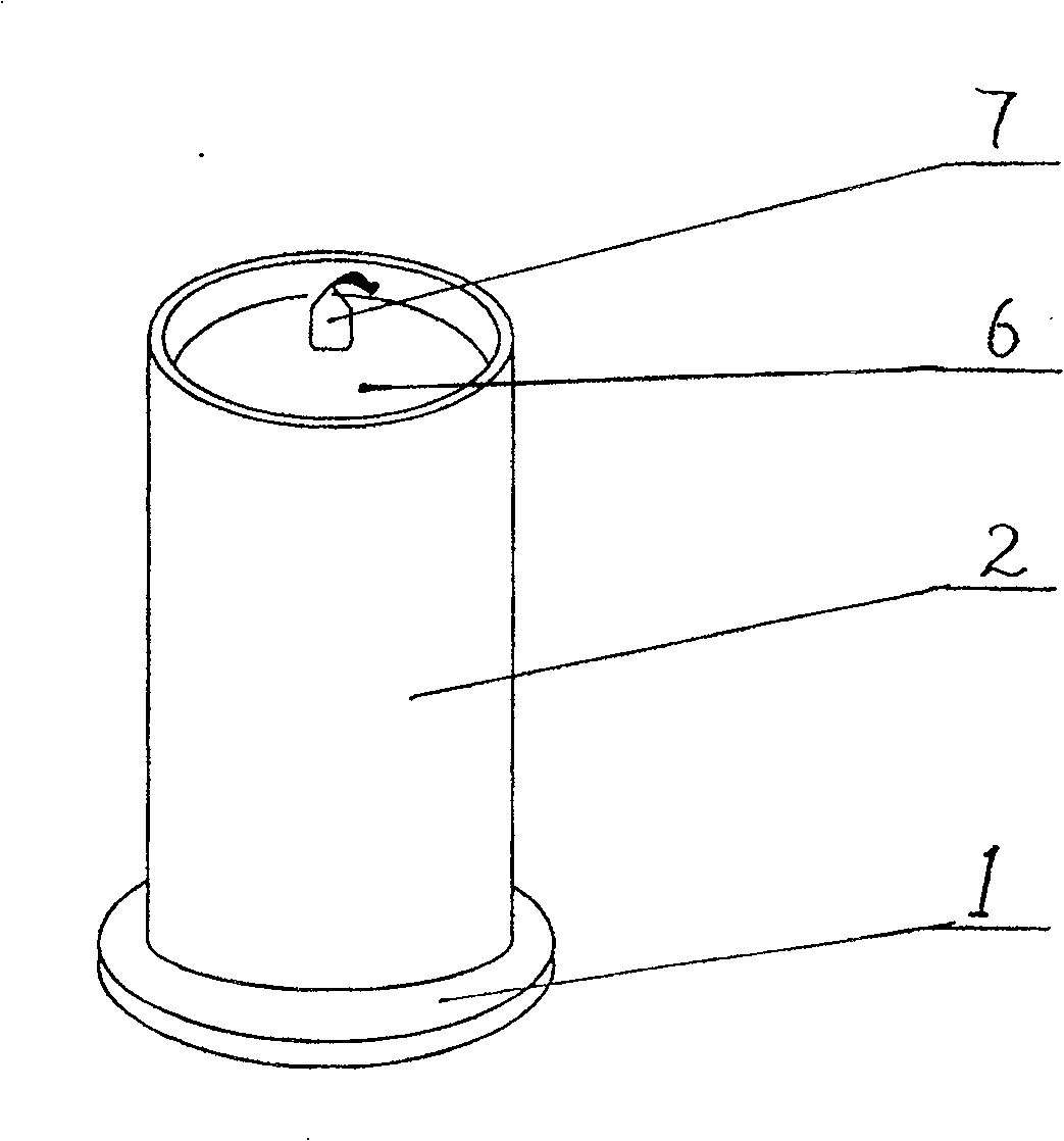
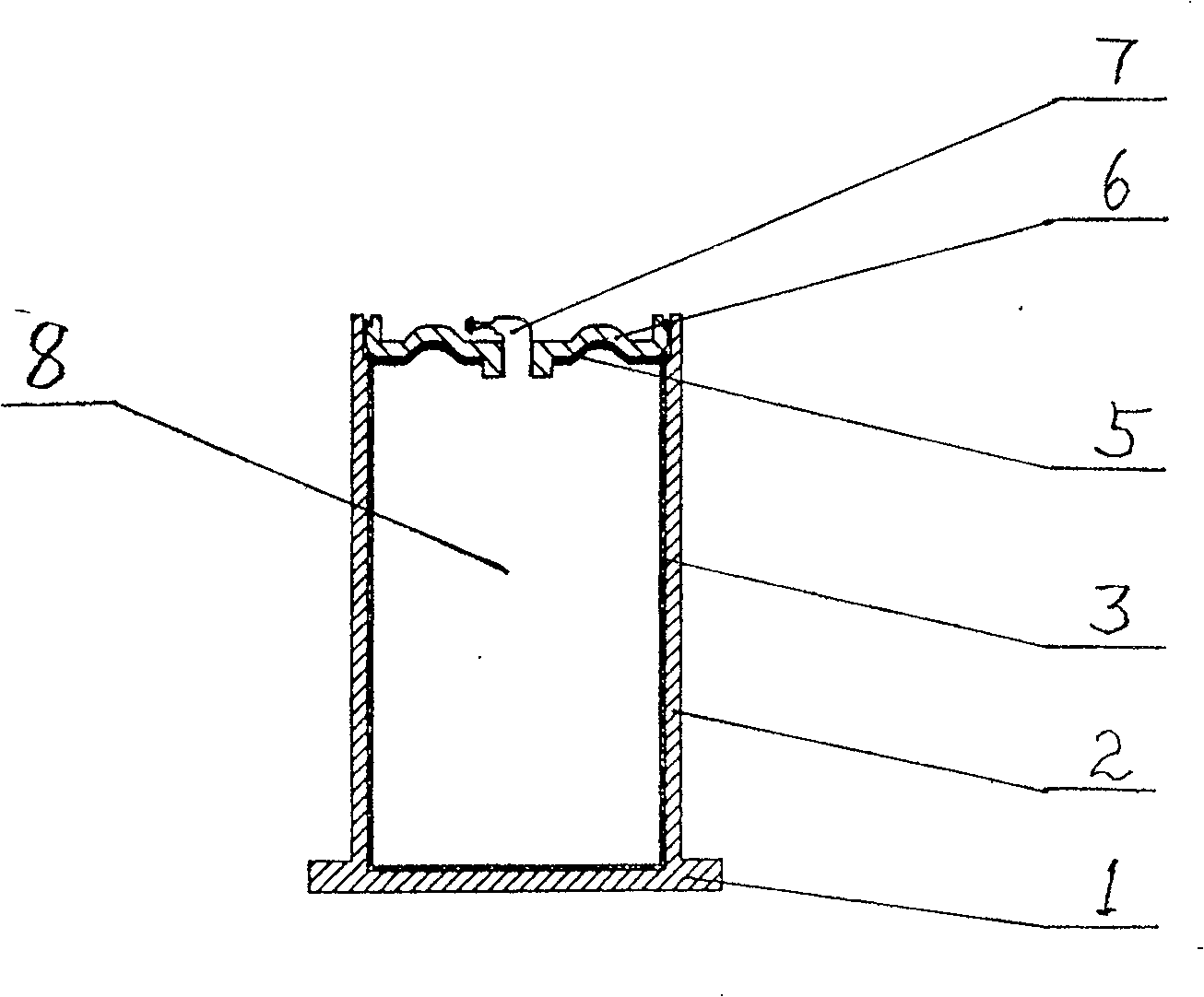
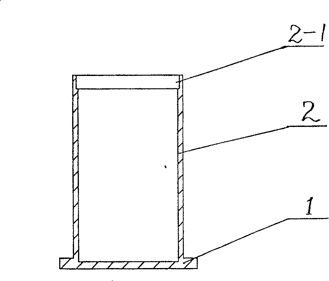
[0029] refer to figure 1 , figure 2 , this cylindrical heat pipe includes a bottom plate 1, a tube body 2, a sintered layer 3, a capillary cover plate 5, a top cover 6, and an exhaust pipe 7. The air pipe 7 forms a sealed cavity 8, and the inside is in a vacuum state; the lower end of the pipe body 2 is provided with a bottom plate 1, and the bottom plate 1 and the pipe body 2 are integrally formed, or two parts are welded together, and the bottom plate 1 and the outer surface of the pipe body 2 The diameters are the same, or the bottom plate 1 is larger than the outer diameter of the pipe body 1, and its shape is circular, or square, or triangular, or rhombus, or other irregular shapes. The upper end of the tube body 2 is provided with a tube body step 2-1, and a capillary cover plate 5 is installed on the tube body step 2-1. The capillary cover plate 5 is made of a wir...


PUM


Abstract

Being composed of floor plate, tube body, top cover and vent-pipe, the column heat pipe is a seal chamber with vacuum state inside. Capillary cover is in upper part, and floor plate is in lower part of the tube. There is sintered layer on inner wall of tube and inner surface of floor plate. The sintered layer connected to capillary cover constitute closed cycle channel of working fluid, which is adsorbed by the sintered layer and the capillary cover. The column heat pipe is prepared through steps: coating metal powder, and carrying out high sintering so as to form sintered layer; installing capillary cover and top cover; inserting vent-pipe; under special atmosphere furnace, high temperature brazing forms sealed chamber except vent-pipe; filling liquid heat transfer working medium from vent-pipe, and drawing out air; sealing vent-pipe. Features are: quick heat conducting rate caused by evaporation of working liquid and condensed phase change, small thermal resistance and light weight.

Description

technical field [0001] The invention relates to a heat pipe and a manufacturing method thereof, in particular to a manufacturing method of a cylindrical heat pipe used for heating the end faces of heating electronic components (including a personal computer CPU). Background technique [0002] With the development and miniaturization of electronic products such as computers, communications, and photoelectric lighting LEDs at an astonishing rate in the "Moore's Law" equivalent series, the relative heat treatment problems are also increasing, and the heat flux is also increasing. How to solve this heat dissipation problem in a limited space and ensure the normal operation of electronic products requires that cooling module manufacturers and related scientific research institutions around the world increase investment in scientific research, actively seek and develop new types of high-efficiency heat dissipation that can meet the development needs of next-generation electronic pr...

Claims


Application Information

Patent Timeline
Patent Type & Authority Patents(China)
IPC IPC(8): F28D15/04
CPCF28D15/02F28D15/0283
Inventor 仝爱星廖仁琦王占篱
Owner 嘉善华昇电子热传科技有限公司
Why Eureka
Try Eureka